×
ToyotaParts- Hello
- Login or Register
- Quick Links
- Live Chat
- Track Order
- Parts Availability
- RMA
- Help Center
- Contact Us
- Shop for
- Toyota Parts
- Scion Parts
My Garage
My Account
Cart
OEM 2005 Toyota Avalon Parking Brake Cable
Emergency Parking Brake Release Cable- Select Vehicle by Model
- Select Vehicle by VIN
Select Vehicle by Model
orMake
Model
Year
Select Vehicle by VIN
For the most accurate results, select vehicle by your VIN (Vehicle Identification Number).
3 Parking Brake Cables found


2005 Toyota Avalon Front Cable
Part Number: 46410-07050$65.40 MSRP: $91.80You Save: $26.40 (29%)Ships in 1-3 Business DaysProduct Specifications- Other Name: Cable Assembly, Parking; Brake Cable; Cable Assembly, Parking Brake
- Part Name Code: 46410
- Item Weight: 2.00 Pounds
- Item Dimensions: 15.7 x 11.6 x 2.9 inches
- Condition: New
- Fitment Type: Direct Replacement
- SKU: 46410-07050
- Warranty: This genuine part is guaranteed by Toyota's factory warranty.

2005 Toyota Avalon Rear Cable
Part Number: 46420-07031$77.72 MSRP: $109.10You Save: $31.38 (29%)Ships in 1-3 Business DaysProduct Specifications- Other Name: Cable Assembly, Parking; Brake Cable
- Replaces: 46420-07030
- Item Weight: 2.60 Pounds
- Item Dimensions: 16.7 x 12.4 x 3.1 inches
- Condition: New
- SKU: 46420-07031
- Warranty: This genuine part is guaranteed by Toyota's factory warranty.
 Product Specifications
- Other Name: Cable Assembly, Parking; Brake Cable
- Replaces: 46430-07030
- Item Weight: 1.40 Pounds
- Condition: New
- SKU: 46430-07031
- Warranty: This genuine part is guaranteed by Toyota's factory warranty.
2005 Toyota Avalon Parking Brake Cable
Looking for affordable OEM 2005 Toyota Avalon Parking Brake Cable? Explore our comprehensive catalogue of genuine 2005 Toyota Avalon Parking Brake Cable. All our parts are covered by the manufacturer's warranty. Plus, our straightforward return policy and speedy delivery service ensure an unparalleled shopping experience. We look forward to your visit!
2005 Toyota Avalon Parking Brake Cable Parts Q&A
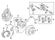
- Q: How to service and repair the Parking Brake Cable Assembly No.3 on 2005 Toyota Avalon?A: The first step to repair or service Parking Brake Cable Assembly No.3 begins with wheel removal followed by separation and removal of the rear disc brake caliper assembly LH and rear disc. The service sequence begins by removing the parking brake shoe return tension spring alongside parking brake shoe strut LH and parking brake shoe. Remove the shift lever knob sub-assembly together with position indicator housing assembly and console panel sub-assembly upper, console box upper and console box assembly from the vehicle. Cable assembly No.4 requires disconnection before removing cable assembly No.3 through the following procedure: remove parking brake equalizer clip and detach two bolts from the backing plate while taking away four bolts and the nut as illustrated followed by unclamping the third brake cable. The installation of parking brake cable assembly No.3 requires connection to the parking brake equalizer followed by securing it with the clip before installing the 4 bolts and nut and clamp while torquing Bolt A to 8.5 Nm (87 kgf-cm, 75 inch lbs.) along with Bolt B and the Nut at 6.0 Nm (61 kgf-cm, 53 inch lbs.) and the two backing plate bolts torqued to 8.0 Nm (82 kgf-cm, 71 inch lbs.). Begin by applying high-temperature grease and proceed to put in the parking brake shoe followed by the parking brake shoe strut LH and the parking brake shoe return tension spring. The procedure requires checking the parking brake installation and adjusting the rear disc before installing the rear disc brake caliper assembly LH and rear wheel while torquing the wheel to 103 Nm (1,050 kgf-cm, 76 ft. lbs.). To finalize the installation, place parking brake cable assembly No.4 together with console box assembly, console panel sub-assembly upper, console box upper and position indicator housing assembly and shift lever knob sub-assembly then check and adjust the parking brake pedal travel.
Related 2005 Toyota Avalon Parts
 2005 Toyota Avalon Wheel Bearing
 2005 Toyota Avalon Brake Caliper
 2005 Toyota Avalon Speed Sensor
 2005 Toyota Avalon Backing Plate
 2005 Toyota Avalon Brake Disc
 2005 Toyota Avalon Brake Line
 2005 Toyota Avalon Brake Pad Set
 2005 Toyota Avalon Brake Shoe Set
 2005 Toyota Avalon Hydraulic Hose
 2005 Toyota Avalon Parking Brake Shoe
 2005 Toyota Avalon Wheel Hub
 2005 Toyota Avalon Wheel Stud