×
ToyotaParts- Hello
- Login or Register
- Quick Links
- Live Chat
- Track Order
- Parts Availability
- RMA
- Help Center
- Contact Us
- Shop for
- Toyota Parts
- Scion Parts
My Garage
My Account
Cart
OEM 2005 Scion tC Sway Bar Kit
Stabilizer Sway Bar Set- Select Vehicle by Model
- Select Vehicle by VIN
Select Vehicle by Model
orMake
Model
Year
Select Vehicle by VIN
For the most accurate results, select vehicle by your VIN (Vehicle Identification Number).
3 Sway Bar Kits found

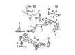
2005 Scion tC Stabilizer Bar, Rear
Part Number: 48812-21030$115.29 MSRP: $161.83You Save: $46.54 (29%)Ships in 1-3 Business DaysProduct Specifications- Other Name: Bar, Stabilizer, Rear; Suspension Stabilizer Bar, Rear; Sway Bar
- Position: Rear
- Part Name Code: 48812
- Item Weight: 5.10 Pounds
- Item Dimensions: 41.6 x 9.1 x 3.5 inches
- Condition: New
- Fitment Type: Direct Replacement
- SKU: 48812-21030
- Warranty: This genuine part is guaranteed by Toyota's factory warranty.

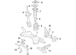
2005 Scion tC Stabilizer Bar, Front
Part Number: 48811-21050$115.29 MSRP: $161.83You Save: $46.54 (29%)Ships in 1-3 Business DaysProduct Specifications- Other Name: Bar, Stabilizer; Suspension Stabilizer Bar, Front; Sway Bar; Bar, Stabilizer, Front
- Position: Front
- Part Name Code: 48811
- Item Weight: 7.90 Pounds
- Item Dimensions: 43.4 x 12.4 x 4.9 inches
- Condition: New
- Fitment Type: Direct Replacement
- SKU: 48811-21050
- Warranty: This genuine part is guaranteed by Toyota's factory warranty.
2005 Scion tC Stabilizer Bar, Rear
Part Number: 48812-21060$96.58 MSRP: $135.56You Save: $38.98 (29%)Ships in 1-3 Business DaysProduct Specifications- Other Name: Bar, Stabilizer, Rear; Suspension Stabilizer Bar, Rear; Sway Bar
- Position: Rear
- Part Name Code: 48812
- Item Weight: 5.10 Pounds
- Item Dimensions: 41.1 x 9.1 x 3.4 inches
- Condition: New
- Fitment Type: Direct Replacement
- SKU: 48812-21060
- Warranty: This genuine part is guaranteed by Toyota's factory warranty.
2005 Scion tC Sway Bar Kit
Looking for affordable OEM 2005 Scion tC Sway Bar Kit? Explore our comprehensive catalogue of genuine 2005 Scion tC Sway Bar Kit. All our parts are covered by the manufacturer's warranty. Plus, our straightforward return policy and speedy delivery service ensure an unparalleled shopping experience. We look forward to your visit!
2005 Scion tC Sway Bar Kit Parts Q&A
- Q: How to replace the rear Sway Bar Kit on 2005 Scion tC?A: You must remove the rear sway bar link assembly LH by uninstalling its two nuts but if the ball joint turns with the nut you should keep the stud still using a 5 mm hexagon (5 mm) wrench. You should follow a similar process to uninstall the rear sway bar link assembly RH. Before installing the nut on the rear sway bar link assembly LH inspect it by operating the ball joint stud 5 times forward and backward then employ a torque wrench to spin the nut for between 2 to 4 seconds per turn while measuring the 5th turn torque to under 1.0 Nm (10 kgf-cm; 8.7 inch lbs.) inspect for any abnormal noises, drag, cracks and dust cover leakage or assembly box deformation. The sway bar rear requires removal after detaching its 2 bolts and 2 nuts and 2 rear sway bar bracket No.3 from the rear suspension member sub-assembly before extracting the 2 sway bar bush rears from the sway bar rear. Position the bush on the stopper ring outer side with the protrusion facing the interior of the vehicle before installing the sway bar rear with its 2 rear sway bar bracket No.3 and 2 bolts and 2 nuts while torquing to 35 Nm (357 kgf-cm, 26 ft. lbs.). Proceed to install the rear sway bar link assembly LH by torquing its 2 nuts to 44 Nm (449 kgf-cm, 32 ft. lbs.). However, if the ball joint rotates with the nut apply a hexagon (5 mm) wrench to secure the stud. Complete installation of the rear sway bar link assembly RH following the LH procedure and inspect then adjust the alignment of the rear wheels.
Related 2005 Scion tC Parts
 2005 Scion tC Ball Joint
 2005 Scion tC Coil Springs
 2005 Scion tC Alignment Bolt
 2005 Scion tC Coil Spring Insulator
 2005 Scion tC Control Arm Bracket
 2005 Scion tC Rear Crossmember
 2005 Scion tC Shock And Strut Mount
 2005 Scion tC Shock and Strut Boot
 2005 Scion tC Suspension Strut Rod
 2005 Scion tC Sway Bar Bracket
 2005 Scion tC Sway Bar Bushing
 2005 Scion tC Sway Bar Link