×
ToyotaParts- Hello
- Login or Register
- Quick Links
- Live Chat
- Track Order
- Parts Availability
- RMA
- Help Center
- Contact Us
- Shop for
- Toyota Parts
- Scion Parts
My Garage
My Account
Cart
OEM 2004 Toyota Sienna Heater Core
HVAC Heater Core- Select Vehicle by Model
- Select Vehicle by VIN
Select Vehicle by Model
orMake
Model
Year
Select Vehicle by VIN
For the most accurate results, select vehicle by your VIN (Vehicle Identification Number).
2 Heater Cores found

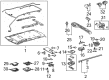
2004 Toyota Sienna Heater Core, Rear
Part Number: 87107-08051$284.71 MSRP: $406.50You Save: $121.79 (30%)Ships in 1-3 Business DaysProduct Specifications- Other Name: Unit Sub-Assembly, Radiator; HVAC Heater Core, Rear; Unit Sub-Assembly, Heater Radiator; HVAC Heater Core
- Manufacturer Note: REAR
- Position: Rear
- Replaces: 87107-08050
- Part Name Code: 87107A
- Item Weight: 6.20 Pounds
- Item Dimensions: 17.9 x 15.5 x 13.3 inches
- Condition: New
- Fitment Type: Direct Replacement
- SKU: 87107-08051
- Warranty: This genuine part is guaranteed by Toyota's factory warranty.

2004 Toyota Sienna Heater Core, Front
Part Number: 87107-08040$357.85 MSRP: $524.44You Save: $166.59 (32%)Ships in 1-3 Business DaysProduct Specifications- Other Name: Unit Sub-Assembly, Radiator; HVAC Heater Core, Front; Unit Sub-Assembly, Heater Radiator; HVAC Heater Core
- Manufacturer Note: FRONT
- Position: Front
- Part Name Code: 87107A
- Item Weight: 1.60 Pounds
- Item Dimensions: 13.4 x 12.0 x 8.6 inches
- Condition: New
- Fitment Type: Direct Replacement
- SKU: 87107-08040
- Warranty: This genuine part is guaranteed by Toyota's factory warranty.
2004 Toyota Sienna Heater Core
Looking for affordable OEM 2004 Toyota Sienna Heater Core? Explore our comprehensive catalogue of genuine 2004 Toyota Sienna Heater Core. All our parts are covered by the manufacturer's warranty. Plus, our straightforward return policy and speedy delivery service ensure an unparalleled shopping experience. We look forward to your visit!
2004 Toyota Sienna Heater Core Parts Q&A
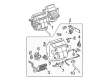
- Q: How to service and repair the heater core and air conditioning radiator assembly on 2004 Toyota Sienna?A: Refrigerant discharging from the refrigeration system should commence with Special Service Tool: 07110-58060 (07117-58080, 07117-58090, 07117-78050, 07117-88060, 07117-88070, 07117-88080) due to its application as a core component. Start the service by removing the front wiper arm head cap followed by both front wiper arms and the cowl top ventilator louver sub-assembly and windshield wiper motor & link assembly. You can disconnect the cowl top panel sub-assembly outer front through the removal of 7 bolts. Use Special Service Tool: 09870-00025 to disconnect the cooler refrigerant liquid pipe E (to cooler unit) without causing any deformation to the pipe. Proceed by using Special Service Tool: 09870-00015 to disconnect the suction hose sub-assembly before removing the air cleaner cap sub-assembly and both heater water outlet hose A and heater water inlet hose A. Complete removal requires taking out the instrument panel sub-assembly with passenger Air Bag assembly and accompanying heater to foot duct No.3 and No.1. Use clamps and nut removal to separate the transmission control cable assembly and shift lock control unit assembly as well as instrument panel bracket No.5. The order is to eliminate instrument panel brace sub-assemblies No.1 and No.2 along with steering column assembly, ECM, stereo component amplifier assembly, front fender garnish RH, and instrument panel reinforcement through removing nuts and clamps and bolts and connectors. Delete the defroster nozzle assembly lower, air conditioning unit assembly, blower assembly, mode damper servo sub-assembly, airmix damper servo sub-assembly, airmix No.2 damper servo sub-assembly, heater clamp No.1, air conditioning radiator brackets No.1, No.2, No.3, and No.4, and air duct No.1. The installation requires new O-rings on the expansion valve before adding compressor oil. Then install the air conditioning tube assembly using new O-rings and torque it to 3.5 Nm (35 kgf.cm, 30 in.lbf). The maintenance technician installs the instrument panel reinforcement by applying 9.8 Nm (100 kgf.cm, 87 in.lbf) on the air conditioning unit assembly before tightening it with 10 bolts, 13 clamps, and 4 nuts to 7.3 Nm (74 kgf.cm, 65 in.lbf). Reinstall the air conditioning unit assembly, shift lock control unit assembly, steering column assembly then the instrument panel sub-assembly with passenger Air Bag assembly in succession. Install the suction hose sub-assembly and cooler refrigerant liquid pipe E (to cooler unit) following its connection by inspecting the claw fittings of the piping clamps. Then lubricate a new O-ring with compressor oil during installation. Check the shift lever position while performing inspections on key interlock and shift lock operations. Add coolant then proceed to charge the refrigerant while using Special Service Tool 07110-58060 (07117-58060, 07117-58070, 07117-58080, 07117-58090, 07117-78050, 07117-88060, 07117-88070, 07117-88080) to reach the required amount of 780 plus or minus 30 g (27.5 plus or minus 1.06 oz.) before the engine reaches operating temperature and conduct inspections for coolant leaks and refrigerant discharge.
Related 2004 Toyota Sienna Parts
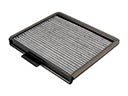 2004 Toyota Sienna Cabin Air Filter
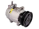 2004 Toyota Sienna A/C Compressor
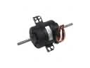 2004 Toyota Sienna Blower Motor
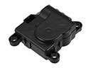 2004 Toyota Sienna Blend Door Actuator
 2004 Toyota Sienna Blower Motor Resistor
 2004 Toyota Sienna A/C Accumulator
 2004 Toyota Sienna A/C Clutch
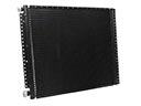 2004 Toyota Sienna A/C Condenser
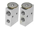 2004 Toyota Sienna A/C Expansion Valve
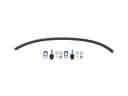 2004 Toyota Sienna A/C Hose
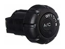 2004 Toyota Sienna A/C Switch
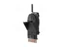 2004 Toyota Sienna Blower Control Switches