×
ToyotaParts- Hello
- Login or Register
- Quick Links
- Live Chat
- Track Order
- Parts Availability
- RMA
- Help Center
- Contact Us
- Shop for
- Toyota Parts
- Scion Parts
My Garage
My Account
Cart
OEM 2004 Toyota Prius Control Arm
Suspension Arm- Select Vehicle by Model
- Select Vehicle by VIN
Select Vehicle by Model
orMake
Model
Year
Select Vehicle by VIN
For the most accurate results, select vehicle by your VIN (Vehicle Identification Number).
2 Control Arms found


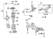
2004 Toyota Prius Lower Control Arm, Driver Side
Part Number: 48069-47040$136.84 MSRP: $193.71You Save: $56.87 (30%)Ships in 1-2 Business DaysProduct Specifications- Other Name: Arm Sub-Assembly, Suspension; Suspension Control Arm, Front Left; Control Arm Assembly; Arm Sub-Assembly, Front Suspension, Lower Driver Side; Control Arm
- Position: Lower Driver Side
- Replaces: 48069-47030
- Part Name Code: 48069
- Item Weight: 7.40 Pounds
- Item Dimensions: 16.6 x 7.2 x 18.3 inches
- Condition: New
- Fitment Type: Direct Replacement
- SKU: 48069-47040
- Warranty: This genuine part is guaranteed by Toyota's factory warranty.

2004 Toyota Prius Lower Control Arm, Passenger Side
Part Number: 48068-47040$136.84 MSRP: $193.71You Save: $56.87 (30%)Ships in 1-3 Business DaysProduct Specifications- Other Name: Arm Sub-Assembly, Suspension; Suspension Control Arm, Front Right; Control Arm Assembly; Arm Sub-Assembly, Front Suspension, Lower Passenger Side; Control Arm
- Position: Passenger Side
- Replaces: 48068-47030
- Part Name Code: 48068
- Item Weight: 7.20 Pounds
- Item Dimensions: 16.3 x 7.1 x 17.8 inches
- Condition: New
- Fitment Type: Direct Replacement
- SKU: 48068-47040
- Warranty: This genuine part is guaranteed by Toyota's factory warranty.
2004 Toyota Prius Control Arm
Looking for affordable OEM 2004 Toyota Prius Control Arm? Explore our comprehensive catalogue of genuine 2004 Toyota Prius Control Arm. All our parts are covered by the manufacturer's warranty. Plus, our straightforward return policy and speedy delivery service ensure an unparalleled shopping experience. We look forward to your visit!
2004 Toyota Prius Control Arm Parts Q&A
- Q: How to replace the front control arm sub-assy lower no.1 LH on 2004 Toyota Prius?A: The 1st LH lower front suspension arm sub-assy requires replacement after users position the front wheels in a straight-ahead direction followed by removing the column hole cover silencer sheet. Start by dividing the steering sliding yoke sub-assy and remove the front wheel and the exhaust pipe assy from the front position. First remove the front axle hub LH nut with Special Service Tool: 09930-00010 before moving on to the front axle hub RH nut. The same procedures must be applied for the RH side. The next step involves the separation of the tie rod end sub-assy LH with Special Service Tool: 09628-00011 then repeating this process for the tie rod end sub-assy RH by following the same steps already applied to the LH side. To detach the front stabilizer link assy users must separate it from the front shock absorber with coil spring while holding the stud stationary with a hexagon (6 mm) wrench to prevent the ball joint from turning with the nut. To remove front suspension arm sub-assy lower No.1 LH you must first detach its bolt and two nuts before lowering it away from the front lower ball joint assy. Apply this procedure to front suspension arm sub-assy lower No.1 RH as well. Remove front axle assy LH and front axle assy RH by repeating previous procedures which were used for the right hand side. To separate the front drive shaft assy LH and the front drive shaft assy RH use Special Service Tool: 09520-01010, 09520-24010 (09520-32040) based on procedures for the RH side. Use the hex wrenches to separate the front suspension crossmember sub-assy and remove the front suspension arm sub-assy lower No.1 LH by loosening its two bolts and nut and maintaining nut rotation stability. Secure the front suspension arm sub-assy lower No.1 LH to the suspension crossmember sub-assy through the temporary installation of its two bolts and nut. Use Special Service Tool: 09670-00010 to mount the front suspension crossmember sub-assy followed by front drive shaft assy LH and front drive shaft assy RH installations which require performing the same steps for the RH side. The installation of front axle assy LH and front axle assy RH will use identical methods as performed on the right hand side. Use the bolt and two nuts to secure the front suspension arm sub-assy lower No.1 LH to the front lower ball joint assy before applying torque of 89 Nm (908 kgf-cm, 66 ft. lbs.). The procedure is repeated for installation of the front suspension arm sub-assy lower No.1 RH. The front stabilizer link assy needs installation by attaching it to the front shock absorber with coil spring through nut torquing to 74 Nm (755 kgf-cm, 55 ft. lbs.) and requiring a hexagon (6 mm) wrench to stabilize the stud if needed. The installation procedure for tie rod end sub-assy LH and tie rod end sub-assy RH should follow the same methodology applied to the RH side. Fasten the front axle hub LH nut while following exactly the same procedure for the right-hand side hub nut. The front tire installation should be followed by vehicle lowering and bouncing to achieve suspension stability before the exhaust pipe front reinstallation. The technician should install the steering sliding yoke sub-assy along with the column hole cover silencer sheet. Tighten the two bolts at 137 Nm (1,400 kgf-cm, 101 ft. lbs.) on the front suspension arm sub-assy lower No.1 LH until the nut stops rotating and then use the 4-pillar lifter to lower the tires to the ground. Finish the task by checking and aligning the front wheel alignment.
Related 2004 Toyota Prius Parts
 2004 Toyota Prius Sway Bar Link
 2004 Toyota Prius Alignment Bolt
 2004 Toyota Prius Bump Stop
 2004 Toyota Prius Coil Spring Insulator
 2004 Toyota Prius Coil Springs
 2004 Toyota Prius Control Arm Bolt
 2004 Toyota Prius Front Cross-Member
 2004 Toyota Prius Shock And Strut Mount
 2004 Toyota Prius Shock and Strut Boot
 2004 Toyota Prius Steering Knuckle
 2004 Toyota Prius Strut Housing
 2004 Toyota Prius Sway Bar Bushing