×
ToyotaParts- Hello
- Login or Register
- Quick Links
- Live Chat
- Track Order
- Parts Availability
- RMA
- Help Center
- Contact Us
- Shop for
- Toyota Parts
- Scion Parts
My Garage
My Account
Cart
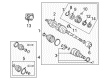
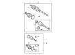
OEM 2004 Toyota Matrix Axle Shaft
Car Axle Shaft- Select Vehicle by Model
- Select Vehicle by VIN
Select Vehicle by Model
orMake
Model
Year
Select Vehicle by VIN
For the most accurate results, select vehicle by your VIN (Vehicle Identification Number).
15 Axle Shafts found

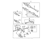
2004 Toyota Matrix Axle Assembly, Rear
Part Number: 42340-32111$347.51 MSRP: $496.17You Save: $148.66 (30%)Ships in 1-3 Business DaysProduct Specifications- Other Name: Shaft Assembly, Rear Drive; CV Axle Assembly, Rear Left, Rear Right; CV Axle Assembly; GSP Cv Axle; Axle Shaft
- Position: Rear
- Replaces: 42340-32110
- Condition: New
- SKU: 42340-32111
- Warranty: This genuine part is guaranteed by Toyota's factory warranty.

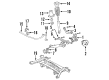
2004 Toyota Matrix Hub & Bearing, Passenger Side
Part Number: 43410-12250$279.58 MSRP: $403.29You Save: $123.71 (31%)Ships in 1-3 Business DaysProduct Specifications- Other Name: Wheel Hub Repair Kit; Wheel Bearing; Axle Bearing; Wheel Hub; Shaft Assembly, Front Drive, Passenger Side
- Position: Passenger Side
- Part Name Code: 43410
- Item Weight: 15.20 Pounds
- Item Dimensions: 29.8 x 7.3 x 6.4 inches
- Condition: New
- Fitment Type: Direct Replacement
- SKU: 43410-12250
- Warranty: This genuine part is guaranteed by Toyota's factory warranty.

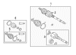
2004 Toyota Matrix Axle Assembly, Driver Side
Part Number: 43420-12590$404.50 MSRP: $592.80You Save: $188.30 (32%)Ships in 1-3 Business DaysProduct Specifications- Other Name: Shaft Assembly, Front Drive; CV Axle Assembly, Front Left; GSP Cv Axle; Axle Shaft; Axle; Shaft Assembly, Front Drive, Driver Side; CV Axle Assembly
- Position: Driver Side
- Part Name Code: 43420
- Item Weight: 18.20 Pounds
- Item Dimensions: 30.1 x 5.1 x 5.1 inches
- Condition: New
- Fitment Type: Direct Replacement
- SKU: 43420-12590
- Warranty: This genuine part is guaranteed by Toyota's factory warranty.

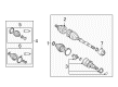
2004 Toyota Matrix Axle Assembly, Driver Side
Part Number: 43420-01070$387.86 MSRP: $568.41You Save: $180.55 (32%)Ships in 1-3 Business DaysProduct Specifications- Other Name: Shaft Assembly, Front Drive; CV Axle Assembly, Front Left; GSP Cv Axle; Axle Shaft; Axle; Shaft Assembly, Front Drive, Driver Side; CV Axle Assembly
- Position: Driver Side
- Part Name Code: 43420
- Item Weight: 14.90 Pounds
- Item Dimensions: 28.9 x 7.3 x 6.4 inches
- Condition: New
- Fitment Type: Direct Replacement
- SKU: 43420-01070
- Warranty: This genuine part is guaranteed by Toyota's factory warranty.
 Product Specifications
- Other Name: Shaft Assembly, Front Drive; CV Axle Assembly, Front Right; GSP Cv Axle; Axle Shaft; Axle; Shaft Assembly, Front Drive, Passenger Side; CV Axle Assembly
- Manufacturer Note: W(ABS)
- Position: Passenger Side
- Part Name Code: 43410
- Item Weight: 14.40 Pounds
- Item Dimensions: 29.5 x 7.3 x 6.5 inches
- Condition: New
- Fitment Type: Direct Replacement
- SKU: 43410-02280
- Warranty: This genuine part is guaranteed by Toyota's factory warranty.
- Product Specifications
- Other Name: Shaft Assembly, Front Drive; CV Axle Assembly, Front Right; GSP Cv Axle; Axle Shaft; Axle; Shaft Assembly, Front Drive, Passenger Side; CV Axle Assembly
- Manufacturer Note: W(ABS)
- Position: Passenger Side
- Part Name Code: 43410
- Item Weight: 25.30 Pounds
- Item Dimensions: 42.8 x 5.6 x 5.4 inches
- Condition: New
- Fitment Type: Direct Replacement
- SKU: 43410-02320
- Warranty: This genuine part is guaranteed by Toyota's factory warranty.
- Product Specifications
- Other Name: Shaft Assembly, Front Drive; CV Axle Assembly, Front Right; GSP Cv Axle; Axle Shaft; Axle; Shaft Assembly, Front Drive, Passenger Side; CV Axle Assembly
- Position: Passenger Side
- Part Name Code: 43410
- Item Weight: 20.20 Pounds
- Item Dimensions: 43.3 x 5.7 x 5.6 inches
- Condition: New
- Fitment Type: Direct Replacement
- SKU: 43410-12630
- Warranty: This genuine part is guaranteed by Toyota's factory warranty.
- Product Specifications
- Other Name: Shaft Assembly, Front Drive; CV Axle Assembly, Front Left; GSP Cv Axle; Axle Shaft; Axle; Shaft Assembly, Front Drive, Driver Side; CV Axle Assembly
- Manufacturer Note: W(ABS)
- Position: Driver Side
- Part Name Code: 43420
- Item Weight: 15.10 Pounds
- Item Dimensions: 28.9 x 7.5 x 6.5 inches
- Condition: New
- Fitment Type: Direct Replacement
- SKU: 43420-01080
- Warranty: This genuine part is guaranteed by Toyota's factory warranty.
- Product Specifications
- Other Name: Shaft Assembly, Front Drive; CV Axle Assembly, Front Right, Rear Right; Axle Shaft; Axle; Shaft Assembly, Front Drive, Passenger Side
- Position: Passenger Side
- Part Name Code: 43410
- Item Weight: 24.30 Pounds
- Item Dimensions: 43.3 x 5.5 x 5.4 inches
- Condition: New
- Fitment Type: Direct Replacement
- SKU: 43410-01100
- Warranty: This genuine part is guaranteed by Toyota's factory warranty.

 Product Specifications
- Other Name: Shaft Assembly, Front Drive; CV Axle Assembly, Front Right; GSP Cv Axle; Axle Shaft; Axle; Shaft Assembly, Front Drive, Passenger Side; CV Axle Assembly
- Position: Passenger Side
- Part Name Code: 43410
- Item Weight: 17.70 Pounds
- Item Dimensions: 44.1 x 6.1 x 6.2 inches
- Condition: New
- Fitment Type: Direct Replacement
- SKU: 43410-02350
- Warranty: This genuine part is guaranteed by Toyota's factory warranty.
2004 Toyota Matrix Axle Assembly, Passenger Side
Part Number: 43410-02310$452.63 MSRP: $663.33You Save: $210.70 (32%)Product Specifications- Other Name: Shaft Assembly, Front Drive; CV Axle Assembly, Front Right; GSP Cv Axle; Axle Shaft; Axle; Shaft Assembly, Front Drive, Passenger Side; CV Axle Assembly
- Position: Passenger Side
- Part Name Code: 43410
- Item Weight: 20.20 Pounds
- Item Dimensions: 49.9 x 6.2 x 6.1 inches
- Condition: New
- Fitment Type: Direct Replacement
- SKU: 43410-02310
- Warranty: This genuine part is guaranteed by Toyota's factory warranty.
- Product Specifications
- Other Name: Shaft Assembly, Front Drive; CV Axle Assembly, Front Left, Rear Left; GSP Cv Axle; Axle Shaft; Axle; Shaft Assembly, Front Drive, Driver Side; CV Axle Assembly
- Position: Driver Side
- Part Name Code: 43420
- Item Weight: 15.40 Pounds
- Item Dimensions: 30.1 x 5.2 x 5.1 inches
- Condition: New
- Fitment Type: Direct Replacement
- SKU: 43420-01090
- Warranty: This genuine part is guaranteed by Toyota's factory warranty.
- Product Specifications
- Other Name: Shaft Assembly, Front Drive; CV Axle Assembly, Front Left; GSP Cv Axle; Axle Shaft; Axle; Shaft Assembly, Front Drive, Driver Side; CV Axle Assembly
- Manufacturer Note: W(ABS)
- Position: Driver Side
- Part Name Code: 43420
- Item Weight: 15.20 Pounds
- Item Dimensions: 29.2 x 7.5 x 6.5 inches
- Condition: New
- Fitment Type: Direct Replacement
- SKU: 43420-02390
- Warranty: This genuine part is guaranteed by Toyota's factory warranty.
 Product Specifications
- Other Name: Shaft Assembly, Front Drive; Axle Shaft; Shaft Assembly, Front Drive, Passenger Side
- Position: Passenger Side
- Part Name Code: 43410
- Item Weight: 24.40 Pounds
- Item Dimensions: 42.4 x 5.5 x 5.4 inches
- Condition: New
- Fitment Type: Direct Replacement
- SKU: 43410-01090
- Warranty: This genuine part is guaranteed by Toyota's factory warranty.
- Product Specifications
- Other Name: Shaft Assembly, Front Drive; CV Axle Assembly, Front Left; GSP Cv Axle; Axle Shaft; Axle; Shaft Assembly, Front Drive, Driver Side; CV Axle Assembly
- Position: Driver Side
- Part Name Code: 43420
- Item Weight: 14.40 Pounds
- Item Dimensions: 29.5 x 7.3 x 6.4 inches
- Condition: New
- Fitment Type: Direct Replacement
- SKU: 43420-01050
- Warranty: This genuine part is guaranteed by Toyota's factory warranty.
2004 Toyota Matrix Axle Shaft
Looking for affordable OEM 2004 Toyota Matrix Axle Shaft? Explore our comprehensive catalogue of genuine 2004 Toyota Matrix Axle Shaft. All our parts are covered by the manufacturer's warranty. Plus, our straightforward return policy and speedy delivery service ensure an unparalleled shopping experience. We look forward to your visit!
2004 Toyota Matrix Axle Shaft Parts Q&A
- Q: How to overhaul the axle shaft assembly on 2004 Toyota Matrix?A: Before beginning the axle shaft assembly overhaul start by draining the manual transaxle oil with a torque of 39.2 Nm (400 kgf-cm, 29 ft. lbs.) and automatic transaxle fluid when using 2WD with 17.5 Nm (178 kgf-cm, 13 ft. lbs.) and when using 4WD with 49 Nm (500 kgf-cm, 36 ft. lbs.). Removing the RH side requires draining transfer oil according to specifications of 49 Nm (500 kgf-cm, 36 ft. lbs.). SST 09930-00010 allows the user to loosen the front axle hub LH nut while applying brake pressure to remove the front wheel along with the engine under cover LH. A hammer is required to unstake the nut. Eliminate the front stabilizer link assembly LH from its connection to the shock absorber assembly front LH while simultaneously detaching the speed sensor front LH (with ABS) that links to the shock absorber and steering knuckle. The LH side tie rod end should be removed with SST 09628-62011 after which you can separate the front suspension arm sub-assembly lower No. 1 LH from its lower ball joint. Use a plastic hammer to determine the front drive shaft assembly LH from the front axle assembly LH by keeping the speed sensor and boot and rotor safe from damage. Levitiate the front drive shaft assembly LH using SST 09520-01010, 09520-24010 (09520-32040) while safeguarding against damage to the oil seal, boot or dust cover. On the RH side maintain the same RH type procedures for all layouts after draining necessary oil from both transaxle and transfer system. SST 09608-16042 (09608-02021, 09608-02041) should be used to fix the front axle assembly LH in order to protect the hub bearing. Check the LH front drive shaft assembly for both boot damage and play during examination while keeping the assembly at level position. Both 2WD and 4WD vehicle types require replacing their inboard joint boot LH clamps which should be done with suitable tools. Before reassembly of the inboard joint sub-assembly LH begins, remove it and clean old grease from the parts. Also mark the alignment to help with reinstallation. For 2WD vehicles install the drive shaft damper in the right position before installing the new part-greased front axle inboard joint sub-assembly LH. Apply both 2WD and 4WD inboard joint boots with clamps while testing their compatibility with SST 09240-00020 (09242-00150). The front drive shaft assemblies must be installed with precise torque specifications for every component while the front axle hub LH nut should be tightened to 216 Nm along with the front wheel assembly at 103 Nm and a fluid inspection and ABS speed sensor check will follow.
Related 2004 Toyota Matrix Parts
 2004 Toyota Matrix CV Joint
 2004 Toyota Matrix Axle Beam Mount
 2004 Toyota Matrix Bump Stop
 2004 Toyota Matrix Coil Spring Insulator
 2004 Toyota Matrix Coil Springs
 2004 Toyota Matrix Control Arm Bushing
 2004 Toyota Matrix Lateral Link
 2004 Toyota Matrix Shock Absorber
 2004 Toyota Matrix Shock And Strut Mount
 2004 Toyota Matrix Suspension Strut Rod
 2004 Toyota Matrix Sway Bar Bushing
 2004 Toyota Matrix Sway Bar Kit