×
ToyotaParts- Hello
- Login or Register
- Quick Links
- Live Chat
- Track Order
- Parts Availability
- RMA
- Help Center
- Contact Us
- Shop for
- Toyota Parts
- Scion Parts
My Garage
My Account
Cart
OEM 2004 Toyota Corolla Cylinder Head Gasket
Engine Cylinder Head Gasket- Select Vehicle by Model
- Select Vehicle by VIN
Select Vehicle by Model
orMake
Model
Year
Select Vehicle by VIN
For the most accurate results, select vehicle by your VIN (Vehicle Identification Number).
1 Cylinder Head Gasket found


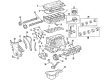
2004 Toyota Corolla Head Gasket
Part Number: 11115-22050$64.45 MSRP: $90.47You Save: $26.02 (29%)Ships in 1 Business DayProduct Specifications- Other Name: Gasket, Cylinder Head; Engine Cylinder Head Gasket; Cylinder Head Gasket; Engine Gasket Set
- Replaces: 11115-22030, 11115-22031, 11115-22040, 11115-22041
- Part Name Code: 11115
- Item Weight: 0.70 Pounds
- Item Dimensions: 25.2 x 8.8 x 0.1 inches
- Condition: New
- Fitment Type: Direct Replacement
- SKU: 11115-22050
- Warranty: This genuine part is guaranteed by Toyota's factory warranty.
2004 Toyota Corolla Cylinder Head Gasket
Looking for affordable OEM 2004 Toyota Corolla Cylinder Head Gasket? Explore our comprehensive catalogue of genuine 2004 Toyota Corolla Cylinder Head Gasket. All our parts are covered by the manufacturer's warranty. Plus, our straightforward return policy and speedy delivery service ensure an unparalleled shopping experience. We look forward to your visit!
2004 Toyota Corolla Cylinder Head Gasket Parts Q&A
- Q: How to replace the cylinder head gasket on 2004 Toyota Corolla?A: Start the cylinder head gasket replacement by blocking gasoline spills and removing the engine under cover RH followed by coolant drainage. The process begins with cylinder head cover No.2 and front wheel RH removal after removing their 2 nuts, 2 clips, and the cover itself. Separate the accelerator control cable by first loosening its bracket mount and then detach its nut before you can remove the air cleaner hose by unplugging its clamp bolts. Disrupt by-pass water hoses at the throttle body before removing the EFI fuel pipe clamp and using Special Service Tool: 09268-21010 to remove the fuel tube sub-assembly. The radiator hose inlet together with the heater inlet water hose must be detached from the cylinder head position. First loosen the V-ribbed belt tensioner to remove the fan and generator V belt after which separate the vane pump assembly without disconnecting the hose. Begin by disconnecting both the 2 bolts holding the generator assembly together with its gasket and the exhaust pipe assembly front. The removal of the engine mounting insulator sub-assembly RH requires first positioning the PS oil pump reservoir aside then installing a wooden block between the jack and engine before removing the 4 bolts and 2 nuts. Remove the engine wire from its connection point after you detach all five clamps on it and four ignition coil connectors and then remove the bolt and nut which keep the wire in place. The ignition coil assembly removal involves unbolted 4 assembly components as well as coil extraction, followed by ventilation hose separation from the cylinder head cover and subsequent removal of the cylinder head cover sub-assembly through the detachment of 9 bolts and 2 seal washers together with 2 nuts and 3 clamp brackets. Position the Number 1 cylinder at TDC / compression alignment through crankshaft pulley groove "0" timing along with proper camshaft timing markers alignment. Start the procedure by using Special Service Tool: 09960-10010 (09962-01000, 09963-01000) to remove the crankshaft pulley followed by taking out the V-ribbed belt tensioner assembly and water pump assembly as well as transverse engine mounting bracket. Remove assembly No.1 of crank position sensor and chain tensioner while avoiding crankshaft rotation unsupported by the chain tensioner. To access all components one must uninstall the timing chain or belt cover sub-assembly along with the timing gear cover oil seal and crankshaft position sensor plate No.1 and chain tensioner slipper and chain vibration damper No.1. Perform these operations in this order: First remove the timing chain with crankshaft timing gear while shielding the engine with shop rag then detach intake manifold by removing water and vacuum hoses and unbolt all components and gasket. Separate the water by-pass pipe No.1 before uniformly loosening and removing the 19 bearing cap bolts to extract the camshafts. Proceed with the removal of the cylinder head sub-assembly by using a specific bolt torquing sequence before proceeding with its detachment. The cylinder head gasket requires replacement with a new one which should display the Lot No. stamp pointing upward during installation while following proper direction orientation. Check the length of the cylinder head set bolt and execute replacement when the measurement goes beyond the maximum length specification. The cylinder head sub-assembly installation requires engine oil application to cylinder head bolts followed by two torque steps to reach 49 Nm (500 kgf-cm, 36 ft. lbs.) before front bolt marking and final 90 degrees bolt tightening according to specified order. After applying installation torque values the mechanic shall install manifold stay and camshaft timing oil control valve assembly and camshafts. Seal the manifold using an new gasket while ensuring a secure connection of all components for water by-pass pipe No.1 and intake manifold and oil level gauge guide. After setting Number 1 cylinder to TDC compression you should install the timing chain sub-assembly chain vibration damper No.1 chain tensioner slipper and crankshaft position sensor plate No.1. Mount the timing gear cover oil seal with Special Service Tool: 09223-22010 followed by installation of the timing chain or belt cover sub-assembly using specified seal packing along with torques indicated. Give your attention to installing the chain tensioner assembly No.1 followed by the crank position sensor and transverse engine mounting bracket along with water pump assembly and V-ribbed belt tensioner assembly according to their specified torque requirements. Install the crankshaft pulley by using Special Service Tool: 09960-10010 (09962-01000, 09963-01000), then verify that the plunger operates as intended. The last step involves installing the cylinder head cover sub-assembly alongside the ignition coil assembly and engine wire and engine mounting insulator sub-assembly RH and exhaust pipe assembly front and vane pump assembly and generator assembly and cylinder head cover No.2 by maintaining all component torques as specified. Reinstall the front wheel on the right while adding coolant to the system and using Special Service Tool: 09992-00500 to check compression. The technician should also examine CO/HC levels and ignition timing using Special Service Tool: 09843-18040 and perform leak inspection of both coolant and oil.
Related 2004 Toyota Corolla Parts
 2004 Toyota Corolla Engine Mount
 2004 Toyota Corolla Timing Chain
 2004 Toyota Corolla Camshaft
 2004 Toyota Corolla Cylinder Head
 2004 Toyota Corolla Dipstick
 2004 Toyota Corolla Dipstick Tube
 2004 Toyota Corolla Timing Chain Tensioner
 2004 Toyota Corolla Crankshaft Pulley
 2004 Toyota Corolla Crankshaft Seal
 2004 Toyota Corolla Intake Valve
 2004 Toyota Corolla Oil Pump Gasket
 2004 Toyota Corolla Timing Cover