×
ToyotaParts- Hello
- Login or Register
- Quick Links
- Live Chat
- Track Order
- Parts Availability
- RMA
- Help Center
- Contact Us
- Shop for
- Toyota Parts
- Scion Parts
My Garage
My Account
Cart
OEM 2004 Toyota 4Runner Brake Master Cylinder
- Select Vehicle by Model
- Select Vehicle by VIN
Select Vehicle by Model
orMake
Model
Year
Select Vehicle by VIN
For the most accurate results, select vehicle by your VIN (Vehicle Identification Number).
2 Brake Master Cylinders found


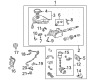
2004 Toyota 4Runner Brake Booster Assembly, W/Master Cylinder
Part Number: 47050-60081$1369.03 MSRP: $2006.33You Save: $637.30 (32%)Ships in 1-3 Business DaysProduct Specifications- Other Name: Cylinder Assembly, Brake; ABS Pump And Motor Assembly; ABS Control Module
- Replaces: 47050-60080
- Part Name Code: 47210L
- Item Weight: 29.60 Pounds
- Item Dimensions: 22.2 x 16.6 x 12.6 inches
- Condition: New
- Fitment Type: Direct Replacement
- SKU: 47050-60081
- Warranty: This genuine part is guaranteed by Toyota's factory warranty.


2004 Toyota 4Runner Cylinder Sub-Assembly, Brake Master
Part Number: 47025-60081$1205.93 MSRP: $1767.30You Save: $561.37 (32%)Ships in 1-2 Business DaysProduct Specifications- Other Name: Cylinder Sub-Assembly, Brake Stroke Simulator; Brake Master Cylinder; Brake Reservoir
- Replaces: 47025-60080
- Part Name Code: 47201
- Item Weight: 17.30 Pounds
- Item Dimensions: 9.0 x 7.2 x 6.0 inches
- Condition: New
- Fitment Type: Direct Replacement
- SKU: 47025-60081
- Warranty: This genuine part is guaranteed by Toyota's factory warranty.
2004 Toyota 4Runner Brake Master Cylinder
Looking for affordable OEM 2004 Toyota 4Runner Brake Master Cylinder? Explore our comprehensive catalogue of genuine 2004 Toyota 4Runner Brake Master Cylinder. All our parts are covered by the manufacturer's warranty. Plus, our straightforward return policy and speedy delivery service ensure an unparalleled shopping experience. We look forward to your visit!
2004 Toyota 4Runner Brake Master Cylinder Parts Q&A
- Q: What steps should be followed before starting the work on the Brake Master Cylinder and brake system on 2004 Toyota 4Runner?A: Begin work when the ignition switch is OFF by additionally releasing the brake pedal more than 40 times to prevent brake actuator tube No.1 from deformation under high-pressure conditions. Remove the instrument panel finish panel, instrument panel finish panel sub-assy lower and instrument panel lower LH as well as skid control ECU assembly and push rod pin after draining brake fluid from a painted surface. To fully remove the parts disconnect them from their clips. Disconnect five connectors from the brake master cylinder followed by using Special Service Tool: 09023-00100 to disconnect the four brake lines while keeping track of them for restablishment. Remove 4 nuts and you will be able to pull out both brake master cylinder and brake booster gasket. The brake master cylinder should be placed in a vise through Special Service Tools: 09630-00014 (09631-00142) and 09950-60010 (09951-00180, 09951-00190). Following this users should loosen and remove lock nuts and rod operating adapter to extract the master cylinder push rod clevis and lock nut. Disconnect the brake level warning connector before removing 3 master cylinder residential screws to take out the boot and master cylinder reservoir sub-assy together with the brake master cylinder reservoir filler cap assembly and 3 reservoir grommets. Push the brake master cylinder plug with a screwdriver to expose the snap ring. Use a pin to push it out before pulling out the brake booster piston, brake booster plug and master cylinder piston with straight motion in order to protect the cylinder bore. Use a hexagon wrench (5 mm) to remove brake actuator brackets No.1, No.4, and No.3 from the vehicle while also using Special Service Tool: 09023-00100 to pull out brake actuator tube No.1 and completing the process by removing the brake actuator hose with needle nose pliers. Disconnect the brake control wire by removing 4 screws and the clamp after which remove the oil pressure sensor and its spacer and O-ring. Start by detaching the brake booster pump brackets No.3 and No.2 afterwards remove the brake booster w/accumulator pump assembly and bracket No.1 afterward take out the two washers and three bushes and two collars as well as the shaft. Inspection of the brake booster pump assembly requires testing with battery leads while using Special Service Tool: 09318-12010. Clean the accumulated brake booster accumulator assembly to prevent foreign debris from entering the pump hardware. Cut down the brake booster accumulator assembly with caution by using a saw according to the designated cutting range. Use Special Service Tool: 09318-12010 to fix the brake booster pump assembly and install the brake booster accumulator assembly together with a new O-ring and pipe at 54 Nm (551 kgf-cm, 40 ft. lbs.). Brake actuator bracket No.3 requires a torque of 7.8 Nm (80 kgf-cm, 69 inch lbs.); proceed with installation of brake booster pump bracket No.2 followed by No.1 at the same torque. The brake booster w/accumulator pump assembly should be installed onto the brake master cylinder before fitting brake booster pump brackets No.2 and No.3 with torques of 11.8 Nm (120 kgf-cm, 9 ft. lbs.). A thickness gauge analysis should verify that the brake booster pump bracket clearance matches the designated specifications. Add the oil pressure sensor with its new O-ring and spacer and tighten it to 74.7 Nm (761 kgf-cm, 55 ft. lbs.) before installing the new brake control wire that will be secured through four screws at the brake booster pump bracket No.2 with a new clamp. Fitting the brake actuator tube No.1 requires a torque of 15.2 Nm (155 kgf-cm, 11 ft. lbs.), while brake actuator bracket No.4 needs a torque setting of 7.8 Nm (80 kgf-cm, 69 inch lbs.). After that, install brake actuator hose and clips. After torquing brake actuator bracket No.1 to 7.8 Nm (80 kgf-cm, 69 inch lbs), apply lithium soap base glycol grease on the master cylinder piston, brake booster piston and brake booster plug before installing them along with a new snap ring. Proceed with installing the 3 new reservoir grommets to the master cylinder reservoir sub-assy and then add the brake master cylinder reservoir filler cap assembly while torquing to 1.7 Nm (17 kgf-cm, 15 inch lbs.) before connecting the brake fluid level warning switch. After installation of the master cylinder boot the mechanic must install the push rod clevis along with its lock nuts and the brake master cylinder at 14.2 Nm while reconnecting 4 brake lines with tool 09023-00100 at 15.2 Nm. The procedure to complete involves installing the push rod pin with its clip along with the skid control ECU assembly, instrument panel lower LH, instrument panel finish panel sub-assy lower and instrument panel finish plate before filling the reservoir with brake fluid followed by bleeding the brake line and inspecting brake pedal height, checking pedal free play, reserve distance, fluid level, leakage and brake master cylinder operation.
Related 2004 Toyota 4Runner Parts
 2004 Toyota 4Runner Brake Caliper
 2004 Toyota 4Runner Speed Sensor
 2004 Toyota 4Runner Wheel Bearing
 2004 Toyota 4Runner Brake Disc
 2004 Toyota 4Runner Brake Shoe Set
 2004 Toyota 4Runner Hydraulic Hose
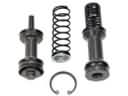 2004 Toyota 4Runner Master Cylinder Repair Kit
 2004 Toyota 4Runner Parking Brake Shoe
 2004 Toyota 4Runner Spindle Nut
 2004 Toyota 4Runner Wheel Cylinder
 2004 Toyota 4Runner Wheel Cylinder Repair Kit
 2004 Toyota 4Runner Yaw Sensor