×
ToyotaParts- Hello
- Login or Register
- Quick Links
- Live Chat
- Track Order
- Parts Availability
- RMA
- Help Center
- Contact Us
- Shop for
- Toyota Parts
- Scion Parts
My Garage
My Account
Cart
OEM 2004 Scion xB Cylinder Head Gasket
Engine Cylinder Head Gasket- Select Vehicle by Model
- Select Vehicle by VIN
Select Vehicle by Model
orMake
Model
Year
Select Vehicle by VIN
For the most accurate results, select vehicle by your VIN (Vehicle Identification Number).
1 Cylinder Head Gasket found


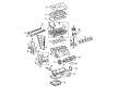
2004 Scion xB Head Gasket
Part Number: 11115-21091$42.05 MSRP: $58.54You Save: $16.49 (29%)Ships in 1-3 Business DaysProduct Specifications- Other Name: Gasket, Cylinder Head; Engine Cylinder Head Gasket; Cylinder Head Gasket; Engine Gasket Set
- Replaces: 11115-21090, 11115-21050, 11115-21030, 11115-21040, 11115-21080
- Part Name Code: 11115
- Item Weight: 0.70 Pounds
- Condition: New
- Fitment Type: Direct Replacement
- SKU: 11115-21091
- Warranty: This genuine part is guaranteed by Toyota's factory warranty.
2004 Scion xB Cylinder Head Gasket
Looking for affordable OEM 2004 Scion xB Cylinder Head Gasket? Explore our comprehensive catalogue of genuine 2004 Scion xB Cylinder Head Gasket. All our parts are covered by the manufacturer's warranty. Plus, our straightforward return policy and speedy delivery service ensure an unparalleled shopping experience. We look forward to your visit!
2004 Scion xB Cylinder Head Gasket Parts Q&A
- Q: How to replace the cylinder head gasket on 2004 Scion xB?A: To replace cylinder head gasket: discharge fuel pressure; remove chain and exhaust; remove exhaust manifold insulator, manifold support, air cleaner, control cable and throttle body; disconnect wiring, hoses and fuel tube; remove intake manifold, camshafts and cylinder head; replace gasket; reinstall and check for leaks.
Related 2004 Scion xB Parts
 2004 Scion xB Oil Filter
 2004 Scion xB Oil Pan
 2004 Scion xB Timing Chain
 2004 Scion xB Valve Cover Gasket
 2004 Scion xB Crankshaft Pulley
 2004 Scion xB Crankshaft Thrust Washer Set
 2004 Scion xB Dipstick Tube
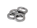 2004 Scion xB Drain Plug Washer
 2004 Scion xB Exhaust Valve
 2004 Scion xB Intake Valve
 2004 Scion xB Oil Pump
 2004 Scion xB Piston Ring Set