×
ToyotaParts- Hello
- Login or Register
- Quick Links
- Live Chat
- Track Order
- Parts Availability
- RMA
- Help Center
- Contact Us
- Shop for
- Toyota Parts
- Scion Parts
My Garage
My Account
Cart
OEM 2003 Toyota Corolla Pressure Plate
Clutch Pressure Plate- Select Vehicle by Model
- Select Vehicle by VIN
Select Vehicle by Model
orMake
Model
Year
Select Vehicle by VIN
For the most accurate results, select vehicle by your VIN (Vehicle Identification Number).
1 Pressure Plate found


2003 Toyota Corolla Pressure Plate
Part Number: 31210-05043$165.55 MSRP: $234.35You Save: $68.80 (30%)Product Specifications- Other Name: Cover Assembly, Clutch; Clutch Kit
- Replaces: 31210-05042, 31210-05041
- Item Weight: 10.20 Pounds
- Item Dimensions: 12.6 x 12.0 x 2.3 inches
- Condition: New
- SKU: 31210-05043
- Warranty: This genuine part is guaranteed by Toyota's factory warranty.
2003 Toyota Corolla Pressure Plate
Looking for affordable OEM 2003 Toyota Corolla Pressure Plate? Explore our comprehensive catalogue of genuine 2003 Toyota Corolla Pressure Plate. All our parts are covered by the manufacturer's warranty. Plus, our straightforward return policy and speedy delivery service ensure an unparalleled shopping experience. We look forward to your visit!
2003 Toyota Corolla Pressure Plate Parts Q&A
- Q: How to overhaul the pressure plate on 2003 Toyota Corolla?A: In order to redo the pressure plate, the transaxle assembly and other parts of the clutch are to be removed and inspected to check the wear and proper measurements. Installation of the clutch disc and cover with matching matchmarks with tightening of bolts to the required torque. Align the check and make necessary adjustments and then re-fit the release fork and transaxle assembly.
Related 2003 Toyota Corolla Parts
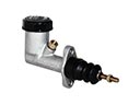 2003 Toyota Corolla Clutch Master Cylinder
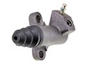 2003 Toyota Corolla Clutch Slave Cylinder
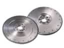 2003 Toyota Corolla Flywheel
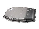 2003 Toyota Corolla Transmission Pan
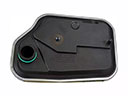 2003 Toyota Corolla Automatic Transmission Filter
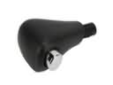 2003 Toyota Corolla Automatic Transmission Shift Levers
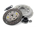 2003 Toyota Corolla Clutch Disc
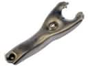 2003 Toyota Corolla Clutch Fork
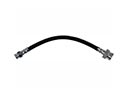 2003 Toyota Corolla Clutch Hose
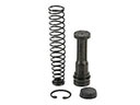 2003 Toyota Corolla Clutch Master Repair Kit
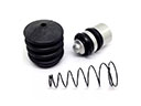 2003 Toyota Corolla Clutch Slave Repair Kit
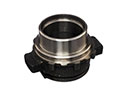 2003 Toyota Corolla Release Bearing