×
ToyotaParts- Hello
- Login or Register
- Quick Links
- Live Chat
- Track Order
- Parts Availability
- RMA
- Help Center
- Contact Us
- Shop for
- Toyota Parts
- Scion Parts
My Garage
My Account
Cart
OEM 2003 Toyota Corolla A/C Compressor
Air Conditioning Compressor- Select Vehicle by Model
- Select Vehicle by VIN
Select Vehicle by Model
orMake
Model
Year
Select Vehicle by VIN
For the most accurate results, select vehicle by your VIN (Vehicle Identification Number).
1 A/C Compressor found

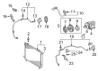
2003 Toyota Corolla Compressor
Part Number: 88320-02120$273.41 MSRP: $390.37You Save: $116.96 (30%)Ships in 1-2 Business DaysProduct Specifications- Other Name: Compressor Assembly; A/C Compressor; New A/C Compressor; Compressor Assembly, Cooler
- Replaces: 88320-02120-84
- Part Name Code: 88320
- Item Weight: 14.10 Pounds
- Item Dimensions: 11.5 x 7.4 x 8.1 inches
- Condition: New
- Fitment Type: Direct Replacement
- SKU: 88320-02120
- Warranty: This genuine part is guaranteed by Toyota's factory warranty.
2003 Toyota Corolla A/C Compressor
Looking for affordable OEM 2003 Toyota Corolla A/C Compressor? Explore our comprehensive catalogue of genuine 2003 Toyota Corolla A/C Compressor. All our parts are covered by the manufacturer's warranty. Plus, our straightforward return policy and speedy delivery service ensure an unparalleled shopping experience. We look forward to your visit!
2003 Toyota Corolla A/C Compressor Parts Q&A
- Q: How to replace the A/C Compressor and its magnetic clutch in a refrigeration system on 2003 Toyota Corolla?A: In order to change the compressor and magnetic clutch, remove the refrigerant, strip the hoses and take parts out. Install the new components, but be sure of correct torque and clearance. Drain oil of the new unit, fill up with refrigerant and check on leakage. Apply specific tools and use torque requirements during the process.
Related 2003 Toyota Corolla Parts
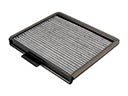 2003 Toyota Corolla Cabin Air Filter
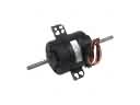 2003 Toyota Corolla Blower Motor
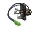 2003 Toyota Corolla Blower Motor Resistor
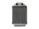 2003 Toyota Corolla Heater Core
 2003 Toyota Corolla A/C Accumulator
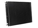 2003 Toyota Corolla A/C Condenser
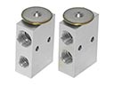 2003 Toyota Corolla A/C Expansion Valve
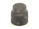 2003 Toyota Corolla A/C Service Cap
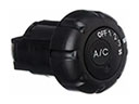 2003 Toyota Corolla A/C Switch
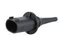 2003 Toyota Corolla Ambient Temperature Sensor
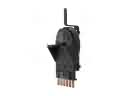 2003 Toyota Corolla Blower Control Switches
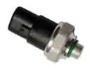 2003 Toyota Corolla HVAC Pressure Switch