×
ToyotaParts- Hello
- Login or Register
- Quick Links
- Live Chat
- Track Order
- Parts Availability
- RMA
- Help Center
- Contact Us
- Shop for
- Toyota Parts
- Scion Parts
My Garage
My Account
Cart
OEM 2003 Toyota 4Runner Wheel Hub
Wheel Axle Hub- Select Vehicle by Model
- Select Vehicle by VIN
Select Vehicle by Model
orMake
Model
Year
Select Vehicle by VIN
For the most accurate results, select vehicle by your VIN (Vehicle Identification Number).
4 Wheel Hubs found


2003 Toyota 4Runner Hub Assembly, Front
Part Number: 43502-60201$171.89 MSRP: $243.33You Save: $71.44 (30%)Ships in 1 Business DayProduct Specifications- Other Name: Hub Sub-Assembly, Front Axle; Wheel Hub, Front; Wheel Hub Repair Kit; Wheel Hub Assembly; Front Hub; Hub; Hub Sub-Assembly, Front Axle, Passenger Side; Hub Sub-Assembly, Front Axle, Driver Side; Wheel Hub
- Position: Front
- Replaces: 43502-60200, 43502-60180
- Item Weight: 1.40 Pounds
- Item Dimensions: 7.1 x 4.1 x 7.3 inches
- Condition: New
- Fitment Type: Direct Replacement
- SKU: 43502-60201
- Warranty: This genuine part is guaranteed by Toyota's factory warranty.


2003 Toyota 4Runner Hub Assembly, Front
Part Number: 43502-35220$189.42 MSRP: $270.44You Save: $81.02 (30%)Ships in 1 Business DayProduct Specifications- Other Name: Hub Sub-Assembly, Front Axle; Wheel Hub, Front; Wheel Bear & Hub Assembly; Wheel Hub Repair Kit; Wheel Hub Module; Front Hub; Hub Sub-Assembly, Front Axle, Passenger Side; Hub Sub-Assembly, Front Axle, Driver Side; Wheel Hub
- Position: Front
- Replaces: 43502-35210
- Item Weight: 1.40 Pounds
- Item Dimensions: 6.9 x 6.4 x 4.7 inches
- Condition: New
- Fitment Type: Direct Replacement
- SKU: 43502-35220
- Warranty: This genuine part is guaranteed by Toyota's factory warranty.


2003 Toyota 4Runner Bearing Housing, Driver Side
Part Number: 42460-60010$344.80 MSRP: $505.32You Save: $160.52 (32%)Ships in 1-2 Business DaysProduct Specifications- Other Name: Bearing Assembly, Rear Axle; Wheel Bearing & Hub; Wheel Hub Repair Kit; Axle Bearing; Axle Bearings; Hub & Bearing; Hub & Bearing Assembly; Hub & Bearing Assembly, Rear Axle, Driver Side
- Position: Driver Side
- Replaces: 42460-60020
- Part Name Code: 42450B
- Item Weight: 2.80 Pounds
- Item Dimensions: 6.9 x 6.9 x 4.7 inches
- Condition: New
- Fitment Type: Direct Replacement
- SKU: 42460-60010
- Warranty: This genuine part is guaranteed by Toyota's factory warranty.

2003 Toyota 4Runner Hub & Bearing Assembly, Rear Axle, Passenger Side
Part Number: 42450-60050$344.80 MSRP: $505.32You Save: $160.52 (32%)Ships in 1 Business DayProduct Specifications- Other Name: Bearing Assembly, Rear Axle; Wheel Bearing & Hub; Repair Kit; Axle Bearing
- Position: Passenger Side
- Replaces: 42450-60060
- Part Name Code: 42450A
- Item Weight: 6.10 Pounds
- Item Dimensions: 7.0 x 7.1 x 4.9 inches
- Condition: New
- Fitment Type: Direct Replacement
- SKU: 42450-60050
- Warranty: This genuine part is guaranteed by Toyota's factory warranty.
2003 Toyota 4Runner Wheel Hub
Looking for affordable OEM 2003 Toyota 4Runner Wheel Hub? Explore our comprehensive catalogue of genuine 2003 Toyota 4Runner Wheel Hub. All our parts are covered by the manufacturer's warranty. Plus, our straightforward return policy and speedy delivery service ensure an unparalleled shopping experience. We look forward to your visit!
2003 Toyota 4Runner Wheel Hub Parts Q&A
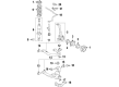
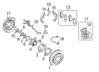
- Q: How to replace the front Wheel Hub sub-assembly on 2003 Toyota 4Runner?A: Start the replacement process of the front axle hub sub-assembly by taking out the front wheel. The speed sensor front LH should be unveiled through hexagon wrench enables to detach two clamps and one bolt for separating the speed sensor wire harness from the steering knuckle. Combining Specific Service Tool: 09023-00100 with the process of disconnecting the brake tube and removing 2 bolts enables removal of the Front Disc Brake Caliper Assembly LH from the steering knuckle. Use a screwdriver combined with a hammer to eliminate the front disc and front axle hub grease cap of the LH side (4WD drive type) while avoiding damage to the axle hub. To remove the front axle hub LH nut start by taking off its lock cap and cotter pin and finishing by unscrewing the nut. A hexagon (6 mm) wrench is required to remove the front stabilizer link assembly LH from the steering knuckle when the ball joint turns with the nut. Special Service Tool: 09628-62011 enables the removal of tie rod end sub-assembly LH followed by front suspension arm sub-assembly lower No.1 LH detachment through two bolt removal. The technician will remove the front front axle hub assembly by using a plastic hammer to separate it from the front drive shaft before removing the front axle hub sub-assembly LH through Special Service Tool: 09628-62011. Begin by removing the knuckle grease retainer cap inner portion with aid of screwdriver and hammer for 2WD drive types and following a similar procedure to remove steering knuckle LH oil seal for 4WD drive types. The process to remove the front axle hub from steering knuckle on 2WD drive types requires Special Service Tool: 09930-00010 09318-12010 and a hammer for unstaking the front wheel adjusting nut LH followed by removal of 4 bolts and axle hub and subsequent O-ring removal from the axle hub. Fix the front axle hub soft inside a vise and remove the bearing with Special Service Tool: 09710-30021 (09710-03051), 09950-40011 (09951-04020, 09952-04010, 09953-04020, 09954-04010, 09955-04061, 09957-04010, 09958-04011). Use a screwdriver to remove the front axle hub LH spacer before installing a new one with a brass bar and hammer while watching for damage formation. Drive the new bearing into position on the front axle hub by using Special Service Tool: 09649-17010 within a press while you install a fresh O-ring along with its dust cover and axle hub using a combination of standard procedure and 4 bolts which need torque setting at 80 Nm (816 kgf-cm, 59 ft. lbs.). Use Special Service Tool: 09318-12010 to install a new adjusting nut which requires a torque setting of 275 Nm (2,804 kgf-cm, 203 ft. lbs.). Similarly, for 4WD drive type installation requires using Special Service Tool: 09527-17011, 09950-70010 (09951-07100), 09951-01000 and a press to install a new steering knuckle LH oil seal. The installation of the new knuckle grease retainer cap inner for 2WD drive type requires use of a brass bar and hammer while taking care not to cause damage. Replace the front axle hub assembly before installing the front suspension upper arm assembly LH with a nut and torque it to 110 Nm (1,122 kgf-cm, 81 ft. lbs.) then fasten with new cotter pin. The front suspension arm sub-assembly lower No.1 LH requires installation with two bolts which need to be torqued to 225 Nm (2,294 kgf-cm, 166 ft. lbs.). Next, install the tie rod end sub-assembly LH with a nut to achieve 91 Nm (928 kgf-cm, 67 ft. lbs.) torque before applying a new cotter pin. The stabilizer link assembly LH should be installed to the steering knuckle with a nut at 70 Nm (714 kgf-cm, 52 ft. lbs.) using a hexagon (6 mm) wrench when possible. First install the front axle hub nut (4WD drive type) to 235 Nm (2,396 kgf-cm, 173 ft. lbs.) then fasten the adjusting cap and secure it with a cotter pin. Torque the front axle hub grease cap LH (4WD drive type) along with the front disc and the front disc brake caliper assembly LH using 2 bolts to 123 Nm (1,254 kgf-cm, 91 ft. lbs.). Then attach the brake tube bracket to the steering knuckle with a bolt torqued to 29 Nm (296 kgf-cm, 21 ft. lbs.) when connecting the brake tube to the disc brake caliper assembly using Special Service Tool: 09023-00100 with a torque setting of 15 Nm (155 kgf-cm, Finally, install the speed sensor front LH by securing the wire harness to the steering knuckle with a bolt, torquing to 13 Nm (133 kgf-cm, 10 ft. lbs.), connecting the 2 clips, and installing the speed sensor with the bolt, torquing to 8.3 Nm (85 kgf-cm, 73 inch lbs.), then bleed the brake line, check the fluid level in the reservoir, inspect for brake fluid leakage, install the front wheel, torquing to 112 Nm (1,142 kgf-cm, 83 ft. lbs.), inspect and adjust the front wheel alignment, and check the ABS speed sensor signal.
Related 2003 Toyota 4Runner Parts
 2003 Toyota 4Runner Brake Pad Set
 2003 Toyota 4Runner Backing Plate
 2003 Toyota 4Runner Brake Caliper Bracket
 2003 Toyota 4Runner Brake Caliper Piston
 2003 Toyota 4Runner Brake Disc
 2003 Toyota 4Runner Brake Master Cylinder Reservoir
 2003 Toyota 4Runner Parking Brake Cable
 2003 Toyota 4Runner Wheel Bearing Dust Cap
 2003 Toyota 4Runner Wheel Cylinder
 2003 Toyota 4Runner Wheel Cylinder Repair Kit
 2003 Toyota 4Runner Wheel Stud
 2003 Toyota 4Runner Yaw Sensor