×
ToyotaParts- Hello
- Login or Register
- Quick Links
- Live Chat
- Track Order
- Parts Availability
- RMA
- Help Center
- Contact Us
- Shop for
- Toyota Parts
- Scion Parts
My Garage
My Account
Cart
OEM 2002 Toyota Tacoma Alternator
Generator- Select Vehicle by Model
- Select Vehicle by VIN
Select Vehicle by Model
orMake
Model
Year
Select Vehicle by VIN
For the most accurate results, select vehicle by your VIN (Vehicle Identification Number).
2 Alternators found


2002 Toyota Tacoma Alternator
Part Number: 27060-62160-84$191.78 MSRP: $255.11You Save: $63.33 (25%)Ships in 1-2 Business DaysProduct Specifications- Other Name: Alternator Assembly, With Regulator
- Replaces: 27060-62160
- Item Weight: 13.20 Pounds
- Item Dimensions: 9.5 x 7.4 x 8.2 inches
- Condition: New
- SKU: 27060-62160-84
- Warranty: This genuine part is guaranteed by Toyota's factory warranty.

2002 Toyota Tacoma Alternator
Part Number: 27060-75160-84$164.79 MSRP: $217.05You Save: $52.26 (25%)Ships in 1-3 Business DaysProduct Specifications- Other Name: Alternator Assembly, With Regulator
- Condition: New
- SKU: 27060-75160-84
- Warranty: This genuine part is guaranteed by Toyota's factory warranty.
2002 Toyota Tacoma Alternator
Looking for affordable OEM 2002 Toyota Tacoma Alternator? Explore our comprehensive catalogue of genuine 2002 Toyota Tacoma Alternator. All our parts are covered by the manufacturer's warranty. Plus, our straightforward return policy and speedy delivery service ensure an unparalleled shopping experience. We look forward to your visit!
2002 Toyota Tacoma Alternator Parts Q&A
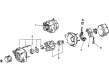
- Q: How to service and repair the alternator on 2002 Toyota Tacoma?A: The alternator servicing process begins with removing both the nut and terminal insulator of the rear end cover before moving on to the three nuts and end cover. Begin servicing the alternator by removing both the brush holder and voltage regulator through the removal of five screws. The next action involves removing the rectifier holder through bolt removal and four screws extraction. First secure SST (A) between a torque wrench and its holder before applying SST (B) clockwise to achieve a 39 N.m torque measurement that prevents SST (A) from loosening from the rotor shaft. SST (C) needs to be mounted in a vise before generator attachment to SST (C) while using SST (A) to adjust the pulley nut as required but never exceeding a half turn for rotor shaft protection. First detach the generator from SST (C) and then detach SST (A) and SST (B) by rotating SST (B). Finish by removing the pulley and its nut. The first step for removing the rectifier end frame includes disassembling its four nuts before using SST 09286-46011 to separate it from the unit. The drive end frame installation begins by fitting the pulley followed by placing the rotor inside then applying the rectifier end frame by inserting the generator washer onto the rotor shaft before using a 29mm socket wrench for pressing followed by tightening four nuts to 4.5 N.m (46 kgf.cm, 40 in.lbf). Fasten the pulley with hand torque to its nut before mounting SST (A) onto the shaft and utilizing a torque wrench on SST (B) to tighten it to 39 N.m (400 kgf.cm, 29 ft.lbf). Inspect for proper shaft-mounting of SST (A). Affix the generator inside SST (C) then mount the device inside a vise before torquing the pulley nut to 110 N.m (1,125 kgf.cm, 81 ft.lbf). Remove the generator from SST (C) then detach SST (A and B). The rectifier holder needs bolt installation with four screws before tightening to 1.96 N.m (20 kgf.cm, 17.4 in.lbf) screw torque and 3.9 N.m (40 kgf.cm, 34.7 in.lbf) bolt torque. Set the voltage regulator horizontally on the rectifier end frame followed by the brush holder installation under careful conditions so the brush holder fits tightly against the connector and torques to 1.96 N.m (20 kgf.cm, 17.4 in.lbf) with five screws. Security of the rear end cover requires torquing it to 4.5 N.m (46 kgf.cm, 40 in.lbf) while terminal insulator installation requires 4.1 N.m (42 kgf.cm, 36 in.lbf) torque to achieve a properly rotating rotor. New brushes demand a wire installation process through the spring and brush holder along with wire soldering at 9.5 to 11.5 mm (0.374 to 0.453 in.) of uncovered wire length. Perform this procedure while ensuring brush holder movement is smooth before welding excess wires and applying insulation paint. The front bearing replacement process requires SST 09950-60010 (09951-00260, 09952-06010) to remove the four screws, bearing retainer and bearing, after which you must press out the bearing with the SST tool to install a new bearing using SST 09950-60010 (09951-00500) while securing the bearing retainer with four screws at 2.6 N.m (26.5 kgf.cm, 23 in.lbf). Use SST to remove the rear bearing cover and bearing being cautious of the fan before placing the inside bearing cover onto the rotor and press in a new bearing with SST 09820-00030 using SST 09285-76010 to install the outer bearing cover.
Related 2002 Toyota Tacoma Parts
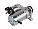 2002 Toyota Tacoma Starter Motor
 2002 Toyota Tacoma Battery Terminal
 2002 Toyota Tacoma Battery Tray
 2002 Toyota Tacoma Starter Solenoid
 2002 Toyota Tacoma Voltage Regulator
 2002 Toyota Tacoma Alternator Bearing
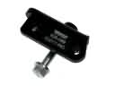 2002 Toyota Tacoma Alternator Bracket
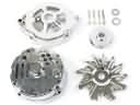 2002 Toyota Tacoma Alternator Case Kit
 2002 Toyota Tacoma Alternator Pulley
 2002 Toyota Tacoma Armature
 2002 Toyota Tacoma Car Batteries
 2002 Toyota Tacoma Starter Brush