×
ToyotaParts- Hello
- Login or Register
- Quick Links
- Live Chat
- Track Order
- Parts Availability
- RMA
- Help Center
- Contact Us
- Shop for
- Toyota Parts
- Scion Parts
My Garage
My Account
Cart
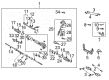
OEM 2002 Toyota MR2 Spyder Rack And Pinion
Steering Rack And Pinion- Select Vehicle by Model
- Select Vehicle by VIN
Select Vehicle by Model
orMake
Model
Year
Select Vehicle by VIN
For the most accurate results, select vehicle by your VIN (Vehicle Identification Number).
2 Rack And Pinions found

 Product Specifications
- Other Name: Gear Assembly, Power Steering; Rack and Pinion Assembly; Steering Gearbox; Gear Assembly; Gear Assembly, Power Steering(For Rack & Pinion)
- Replaces: 44250-17080, 44200-17081
- Part Name Code: 44250
- Item Weight: 17.00 Pounds
- Item Dimensions: 56.0 x 11.7 x 6.8 inches
- Condition: New
- Fitment Type: Direct Replacement
- SKU: 44250-17081
- Warranty: This genuine part is guaranteed by Toyota's factory warranty.
 Product Specifications
- Other Name: Rack Sub-Assembly, Power; Rack And Pinion Rack Gear, Front; Steering Gearbox; Steering Rack; Rack; Rack Sub-Assembly, Power Steering
- Position: Front
- Part Name Code: 44204
- Item Weight: 5.40 Pounds
- Item Dimensions: 32.4 x 3.1 x 2.8 inches
- Condition: New
- Fitment Type: Direct Replacement
- SKU: 44204-17060
- Warranty: This genuine part is guaranteed by Toyota's factory warranty.
2002 Toyota MR2 Spyder Rack And Pinion
Looking for affordable OEM 2002 Toyota MR2 Spyder Rack And Pinion? Explore our comprehensive catalogue of genuine 2002 Toyota MR2 Spyder Rack And Pinion. All our parts are covered by the manufacturer's warranty. Plus, our straightforward return policy and speedy delivery service ensure an unparalleled shopping experience. We look forward to your visit!
2002 Toyota MR2 Spyder Rack And Pinion Parts Q&A
- Q: How to disassemble the Rack And Pinion on 2002 Toyota MR2 Spyder?A: Start by detaching the 2 turn pressure tubes through the use of Special Service Tool: 09023-38200 followed by removal of the 4 O-rings. A vise attachment of the Rack And Pinion assembly requires Special Service Tool: 09612-00012. Begin by marking both tie rod ends and rack ends before easing off the lock nut and removing the tie rod ends with lock nuts. Unfasten the clamp with a screwdriver tool to take off clips, clamps, and rack boots while protecting their condition. Apply Special Service Tool: 09922-10010 to the LH rack end before removing it. Handle the RH rack end in the same manner. Use Special Service Tool: 09922-10010 to uninstall the rack guide spring cap lock nut. Then use the 19 mm hexagon wrench to unwind the rack guide spring cap and spring and subassembly. Secondly use Special Service Tool: 09616-00011 to remove both the rack housing cap along with the self-locking nut after that sequence. Remove the control valve housing with its assembly by first removing the dust seal followed by marking the housing before extraction. Avoid damaging the oil seal lip while you use vinyl tape to wrap the shaft of the control valve before extracting the control valve assembly. First extract the control valve assembly oil seal before using needle nose pliers to remove the snap ring then taking out the cylinder end stopper. Special Service Tool: 09950-70010 (09951-07200) helps users press out the rack and pinion with bushing before removing the O-ring from the bushing. During inspection use a dial indicator to examine the rack and pinion for all three parameters with maximum allowed runout at 0.1 mm (0.004 inch). The oil seal replacement for the rack housing requires using Special Service Tool: 09950-60010 (09951-00210 and 09951-00240 and 09952-06010) to extract the oil seal and then installing the new seal by dipping its lip in power steering fluid using the same tool. Special Service Tools 09950-60010 (09951-00260) and 09950-70010 (09951-07100) must be used to correctly install both the control valve housing oil seal and bearing. The No. 1 and No. 2 bearings of the rack housing require bearing extraction using a screwdriver and hammer before application of molybdenum disulfide lithium base grease followed by insertion with Special Service Tools: 09950-60010 (09951-00220, 09951-00320, 09951-00420, 09951-00430, 09952-06010) and 09950-70010 (09951-07100). To replace the rack and pinion bushing oil seal properly install Special Service Tools 09612-24014 (09613-22011), apply power steering fluid to a new oil seal lip and utilize Special Service Tool 09950-60010 (09951-00210, 09951-00350, 09952-06010) for insertion. Install a new O-ring by applying power steering fluid on it before placing it into the rack and pinion. The new Teflon ring requires expansion followed by fluid coating before its installation. The 4 Teflon rings need removal from the control valve assembly before installing expanded new rings that require power steering fluid application for each piece. You should use power steering fluid or molybdenum disulfide lithium base grease to coat designated parts during reassembly and install the rack and pinion with Special Service Tool: 09631-10041 while coating it with power steering fluid prior to removing the tool. When installing the bushing of the rack and pinion be cautious to avoid damage to the oil seal lips while also installing the cylinder end stopper together with its snap ring. Perform an air tightness test by using Special Service Tool: 09631-12071 (09633-00010) with streaming vacuum measurement checks. Place the control valve assembly correctly while avoiding Teflon rings and oil seal lips damage and then set the oil seal into place with Special Service Tool: 09612-22011. Mount the control valve housing with its fresh gasket while matching the marks before tightening bolts to 21 Nm (210 kgf-cm, 15 ft. lbs.). Secure the dust seal and self-locking nut using Tool: 09616-00010 while torquing it to 24.5 Nm (250 kgf-cm, 18 ft. lbs.). Apply sealant on rack housing cap threads before installing the cap with a torque value of 59 Nm (600 kgf-cm, 43 ft. lbs.) and perform staking operations on the cap. Mount the rack guide sub-assembly followed by the rack guide spring and rack guide spring cap while sealing both threads with specified materials. To perform total preload adjustment the mechanic should install the RH and LH rack ends and torque the rack guide spring cap to 25 Nm (250 kgf-cm, 18 ft. lbs.) before turning it 12 degrees. Use the Special Service Tool: 09616-00011 to rotate the control valve shaft before adjusting the rack guide spring cap through loosening until it stops functioning due to a preload range of 0.8 - 1.3 Nm (8 - 13 kgf-cm, 6.9 - 11.3 inch lbs.). Sealant the rack guide spring cap lock nut before torquing it to 28 Nm (290 kgf-cm, 21 ft. lbs.) and verify the total preload one more time. The last steps involve installing RH and LH rack ends with matching marks aligned while torquing nuts to 47 Nm (480 kgf-cm, 35 ft. lbs.) then applying RH and LH rack boots and clamps with clips while checking for grease clogging the rack and pinion end hole, all by using Special Service Tool: 09521-24010.
Related 2002 Toyota MR2 Spyder Parts
 2002 Toyota MR2 Spyder Power Steering Pump
 2002 Toyota MR2 Spyder Steering Wheel
 2002 Toyota MR2 Spyder Drag Link
 2002 Toyota MR2 Spyder Ignition Switch
 2002 Toyota MR2 Spyder Power Steering Control Valve
 2002 Toyota MR2 Spyder Power Steering Hose
 2002 Toyota MR2 Spyder Rack and Pinion Boot
 2002 Toyota MR2 Spyder Steering Column Cover
 2002 Toyota MR2 Spyder Steering Gear Box
 2002 Toyota MR2 Spyder Steering Shaft
 2002 Toyota MR2 Spyder Tie Rod End
 2002 Toyota MR2 Spyder Wiper Switch