×
ToyotaParts- Hello
- Login or Register
- Quick Links
- Live Chat
- Track Order
- Parts Availability
- RMA
- Help Center
- Contact Us
- Shop for
- Toyota Parts
- Scion Parts
My Garage
My Account
Cart
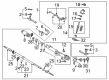
OEM 2001 Toyota Sequoia Rack And Pinion
Steering Rack And Pinion- Select Vehicle by Model
- Select Vehicle by VIN
Select Vehicle by Model
orMake
Model
Year
Select Vehicle by VIN
For the most accurate results, select vehicle by your VIN (Vehicle Identification Number).
2 Rack And Pinions found


 Product Specifications
- Other Name: Rack Sub-Assembly, Power; Rack And Pinion Rack Gear, Front; Steering Gearbox; Steering Rack; Rack Sub-Assembly, Power Steering
- Position: Front
- Part Name Code: 44204
- Item Weight: 5.40 Pounds
- Item Dimensions: 32.7 x 3.2 x 2.8 inches
- Condition: New
- Fitment Type: Direct Replacement
- SKU: 44204-0C010
- Warranty: This genuine part is guaranteed by Toyota's factory warranty.

2001 Toyota Sequoia Steering Gear
Part Number: 44250-0C041$722.76 MSRP: $1059.21You Save: $336.45 (32%)Product Specifications- Other Name: Gear Assembly, Power Steering; Rack and Pinion Assembly; Steering Gearbox; Rack & Pinion; Gear Assembly; Gear Assembly, Power Steering(For Rack & Pinion)
- Manufacturer Note: W(REAR STABILIZER)
- Replaces: 44250-0C050, 44250-0C020
- Part Name Code: 44250
- Item Weight: 1.40 Pounds
- Item Dimensions: 3.4 x 3.2 x 3.5 inches
- Condition: New
- Fitment Type: Direct Replacement
- SKU: 44250-0C041
- Warranty: This genuine part is guaranteed by Toyota's factory warranty.
2001 Toyota Sequoia Rack And Pinion
Looking for affordable OEM 2001 Toyota Sequoia Rack And Pinion? Explore our comprehensive catalogue of genuine 2001 Toyota Sequoia Rack And Pinion. All our parts are covered by the manufacturer's warranty. Plus, our straightforward return policy and speedy delivery service ensure an unparalleled shopping experience. We look forward to your visit!
2001 Toyota Sequoia Rack And Pinion Parts Q&A
- Q: How to disassemble the Rack And Pinion on 2001 Toyota Sequoia?A: The first step to disassemble the rack and pinion begins with removing 2 turn pressure tubes using Special Service Tool: 09023-38400 before extracting all 4 O-rings. The Rack And Pinion assembly needs to be secured within a vise through the combination of Special Service Tool: 09612-00012 and 2 bolts (90105-10346) and nuts (90170-10198). Write a mark on the tie rod end along with its lock nut and rack end before taking out right-hand and left-hand tie rod ends and lock nuts. A screwdriver should be used to loosen the 2 clamps before removing the right-hand and left-hand clips together with rack boots and clamps while maintaining boot integrity. Start by marking the rack and pinion then unstake the claw washers with a screwdriver and hammer while using a spanner to hold the rack and pinion before removing the right-hand and left-hand rack ends using Special Service Tool: 09922-10010. Remove the rack guide spring cap lock nut using Special Service Tool: 09922-10010 before extracting the rack guide spring cap, rack guide spring and rack guide sub-assembly by using a hexagon wrench. You can remove the rack housing cap with Special Service Tool: 09816-30010 while using Special Service Tool: 09616-00011 to halt control valve shaft rotation and take out the self-locking nut. Begin by removing the control valve housing together with its assembly through matching the identified marks before removing the gasket. The procedure for safeguarding the oil seal lip begins with application of vinyl tape on the valve shaft followed by pressurizing the valve assembly with the oil seal while inserting a shop rag between the valve housing and blocks. The control valve assembly removal process begins by extracting its oil seal. Next, use Special Service Tool: 09631-16010 to rotate the cylinder end stopper clockwise as the wire end becomes visible while counterclockwise rotation removes the wire. Use Special Service Tool: 09950-70010 (09951-07200) to press the rack and pinion with its bushing but keep the rack from falling before removing the bushing and O-ring. Proceed with oil seal pressing operations using Special Service Tool: 09950-60010 (09951-00360), 09950-70010 (09951-07360). A dial indicator should be used to check the rack and pinion for runout which should remain below 0.03 mm (0.0118 inch) while inspecting for damage and wear in the teeth. Press the new oil seal into place with Special Service Tool: 09950-60010 (09951-00180, 09951-00320, 09952-06010) after initially waterproofing the seal lip with power steering fluid and using the tool with numbers (09951-00250 and 09951-07150). New bearings require molybdenum disulfide lithium base grease application before their installation with appropriate tools. The installation of a bushing oil seal requires Special Service Tool: 09527-20011, 09612-24014 (09613-22011) to perform the operation without damaging the bushing. The installation of a new rack and pinion requires expanding the teflon ring gently after coating the O-ring with power steering fluid. Prepare teflon rings for the control valve installation by avoiding contact with the grooves. To reassemble the parts need power steering fluid or molybdenum disulfide lithium base grease coating, use Special Service Tool: 09950-60010 (09951-00330, 09951-00490, 09952-06010) to install the oil seal with the correct orientation. Then add the rack and pinion to the bushing with a new O-ring that received coating in power steering fluid. Install the end stopper of the cylinder while aligning its wire installation hole then check for air tightness using Special Service Tool: 09631-12071. Executable Procedure: Avoid oil seal lip damage while assembling the control valve components together then apply Special Service Tool: 09612-22011 to press in the oil seal. Mount the control valve housing together with the control valve assembly by matching marks and fasten the two bolts with 18 Nm (185 kgf-cm, 13 ft. lbs.) torque. First secure the self-locking nut at 25 Nm torque (250 kgf-cm, 18 ft. lbs.) and continue to install the dust cover alongside the rack housing cap by applying sealant to threads and tightening them using Special Service Tool: 09816-30010 at 59 Nm torque (600 kgf-cm, 43 ft. lbs.). Stake the cap components before installing both the rack guide sub-assembly along with its rack guide spring and rack guide spring cap by applying sealant to all threads. Total preload adjustment occurs when the rack ends are installed temporarily with rack guide spring cap torqued to 25 Nm (250 kgf-cm, 18 ft. lbs.) until it reaches the 12 degrees mark. Turn the control valve shaft using Special Service Tool 09616-00011 to relay the rack guide spring cap until no functionality remains and finish tightening the cap to a preload range between 1.2 - 1.6 Nm (12 - 16 kgf-cm, 10.4 - 13.9 inch lbs.). Apply sealant to the rack guide spring cap lock nut before tightening it to 44 Nm (450 kgf-cm, 32 ft. lbs.) while checking the total preload once more. The last step involves installing both right-hand and left-hand rack ends while maintaining their matchmark alignment and torquing the lock nut to 55 Nm (560 kgf-cm, 41 ft. lbs.). The racks require two-tightening pressure tubes fitted with new O-rings before torquing them to 13 Nm (135 kgf-cm, 10 ft. lbs.).
Related 2001 Toyota Sequoia Parts
 2001 Toyota Sequoia Power Steering Pump
 2001 Toyota Sequoia Steering Angle Sensor
 2001 Toyota Sequoia Steering Wheel
 2001 Toyota Sequoia Drag Link
 2001 Toyota Sequoia Power Steering Control Valve
 2001 Toyota Sequoia Power Steering Hose
 2001 Toyota Sequoia Power Steering Reservoir
 2001 Toyota Sequoia Rack and Pinion Boot
 2001 Toyota Sequoia Steering Column Cover
 2001 Toyota Sequoia Steering Gear Box
 2001 Toyota Sequoia Steering Shaft
 2001 Toyota Sequoia Tie Rod End