×
ToyotaParts- Hello
- Login or Register
- Quick Links
- Live Chat
- Track Order
- Parts Availability
- RMA
- Help Center
- Contact Us
- Shop for
- Toyota Parts
- Scion Parts
My Garage
My Account
Cart
OEM 2000 Toyota MR2 Spyder Starter Motor
Starter Ignition- Select Vehicle by Model
- Select Vehicle by VIN
Select Vehicle by Model
orMake
Model
Year
Select Vehicle by VIN
For the most accurate results, select vehicle by your VIN (Vehicle Identification Number).
1 Starter Motor found

 Product Specifications
- Other Name: Reman Starter Assembly; Starter Motor
- Replaces: 28100-22060
- Item Weight: 9.30 Pounds
- Item Dimensions: 10.3 x 7.1 x 5.1 inches
- Condition: New
- SKU: 28100-22060-84
- Warranty: This genuine part is guaranteed by Toyota's factory warranty.
2000 Toyota MR2 Spyder Starter Motor
Looking for affordable OEM 2000 Toyota MR2 Spyder Starter Motor? Explore our comprehensive catalogue of genuine 2000 Toyota MR2 Spyder Starter Motor. All our parts are covered by the manufacturer's warranty. Plus, our straightforward return policy and speedy delivery service ensure an unparalleled shopping experience. We look forward to your visit!
2000 Toyota MR2 Spyder Starter Motor Parts Q&A
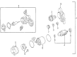
- Q: How to service and repair the starter motor on 2000 Toyota MR2 Spyder?A: Repairing the starter motor begins with complete disassembly which requires wrenches and wire cutters to remove the nut and disconnect the switch terminal lead wire from the magnetic device along with unscrewing both field frame bolts to remove the assembly and field frame with the armature before removing the O-rings and screws securing the end cover from the field frame and at last removing the O-ring from the field frame. Screwdrivers can be used to maintain spring tank backward position and separate the brush from the brush holder before removing four brushes along with the brush holder. Take out the 2 bolts to remove the starter housing followed by elimination of the starter housing (1) idler gear (2) bearing (3) clutch assembly (4) and return spring (5) from the magnetic switch assembly. The steel ball extraction requires a magnetic finger tool in the clutch shaft hole. To reassemble the device start by applying high-temperature grease on all bearings and gears before attaching the armature to the magnetic switch assembly after greasing its bearings. To install the starter housing and clutch assembly with their accompanying gears you must first oil the return spring by applying grease to it then feed it into the magnetic switch hole before placing the starter clutch assembly onto the starter housing and the idler and bearing assembly and securing the 2 bolts with a torque of 5.9 Nm (60 kg.cm, 52 in.lb). Set the O-ring inside the field frame groove then position it correctly by the magnetic switch before installation. Installation process starts by attaching the brush holder to the field frame while a screwdriver stretches the brush spring for wire connection with attention to prevent the positive (+) lead wires from becoming grounded. Use one of the new O-rings on the field frame groove then attach the end cover using 2 screws tightened to 1.5 Nm (15 kg.cm, 13 in.lb) before securing the field frame-armature assembly through two bolts at 5.9 Nm (60 kg.cm, 52 in.lb) torque while connecting the lead wire to terminal C with the nut tightened to 5.9 Nm (60 kg.cm, 52 in.lb). Users should employ Special Service Tool: 09286-6011 to extract the bearing before performing bearing replacement with Special Service Tool: 09820-00030 and a press for the front bearing installation followed by similarpressing of the rear bearing. Measure the contact plate depth for wear because any readings exceeding 0.9 mm (0.035 in.) require replacement of the magnetic switch terminal kit parts by first removing the end cover, gasket and plunger and three bolts before inspection. Use Special Service Tool: 09810-38140 to remove terminal nuts from the parts within the kit while uninstalling Terminal C and Terminal 30 components, but first install new terminal 30 parts in the correct direction for the terminal insulator. The terminal C kit parts receive temporary tightening then Special Service Tool: 0981-38140 functions to press the contact plate with force 981 N (100 kg, 221 lb) and reaches torque level 17 Nm (170 kg.cm, 12 ft.lb). The contact plate and plunger must be cleaned before reinstalling the magnetic switch end cover including the plunger and new gasket while tightening three bolts with 2.5 Nm torque (26 kg.cm, 23 in.lb).
Related 2000 Toyota MR2 Spyder Parts
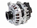 2000 Toyota MR2 Spyder Alternator
 2000 Toyota MR2 Spyder Alternator Bearing
 2000 Toyota MR2 Spyder Alternator Brush
 2000 Toyota MR2 Spyder Alternator Pulley
 2000 Toyota MR2 Spyder Armature
 2000 Toyota MR2 Spyder Battery Terminal
 2000 Toyota MR2 Spyder Battery Tray
 2000 Toyota MR2 Spyder Car Batteries
 2000 Toyota MR2 Spyder Starter Brush
 2000 Toyota MR2 Spyder Starter Drive Gear
 2000 Toyota MR2 Spyder Starter Solenoid
 2000 Toyota MR2 Spyder Voltage Regulator