×
ToyotaParts- Hello
- Login or Register
- Quick Links
- Live Chat
- Track Order
- Parts Availability
- RMA
- Help Center
- Contact Us
- Shop for
- Toyota Parts
- Scion Parts
My Garage
My Account
Cart
OEM Toyota Highlander Fuel Level Sensor
Gas Gauge Sensor- Select Vehicle by Model
- Select Vehicle by VIN
Select Vehicle by Model
orMake
Model
Year
Select Vehicle by VIN
For the most accurate results, select vehicle by your VIN (Vehicle Identification Number).
11 Fuel Level Sensors found


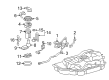
Toyota Highlander Fuel Gauge Sending Unit Part Number: 83320-48040
$87.44 MSRP: $122.74You Save: $35.30 (29%)Ships in 1-2 Business Days

Toyota Highlander Pressure Sensor Part Number: 89458-06021
$170.25 MSRP: $241.00You Save: $70.75 (30%)Ships in 1-3 Business Days
Toyota Highlander Gage Assembly, Fuel Sender Part Number: 83320-48100
$145.92 MSRP: $206.57You Save: $60.65 (30%)Ships in 1-3 Business Days
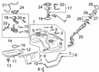
Toyota Highlander Fuel Filter Part Number: 77024-0E150
$204.80 MSRP: $292.40You Save: $87.60 (30%)Ships in 1-2 Business Days
Toyota Highlander Fuel Gauge Sending Unit Part Number: 83320-0E061
$75.95 MSRP: $106.60You Save: $30.65 (29%)Ships in 1-3 Business Days
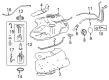
Toyota Highlander Fuel Gauge Sending Unit Part Number: 83320-0E050
$75.95 MSRP: $106.60You Save: $30.65 (29%)Ships in 1-3 Business DaysToyota Highlander Gage Assembly, Fuel Sender Part Number: 83320-0E030
$88.63 MSRP: $124.40You Save: $35.77 (29%)Ships in 1-3 Business Days
Toyota Highlander Gage Assembly, Fuel Sender Part Number: 83320-0E010
$97.16 MSRP: $136.38You Save: $39.22 (29%)Ships in 1-3 Business Days
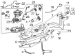
Toyota Highlander Fuel Sender Unit Part Number: 83320-48012
$100.00 MSRP: $140.37You Save: $40.37 (29%)Ships in 1-3 Business Days
Toyota Highlander Fuel Gauge Sending Unit Part Number: 83320-48121
$100.36 MSRP: $140.87You Save: $40.51 (29%)Ships in 1-3 Business Days
Toyota Highlander Fuel Gauge Sending Unit Part Number: 83320-49175
Toyota Highlander Fuel Level Sensor
Choose genuine Fuel Level Sensor that pass strict quality control tests. You can trust the top quality and lasting durability. Shopping for OEM Fuel Level Sensor for your Toyota Highlander? Our website is your one-stop destination. We stock an extensive selection of genuine Toyota Highlander parts. The price is affordable so you can save more. It only takes minutes to browse and find the exact fit. Easily add to cart and check out fast. Our hassle-free return policy will keep you stress-free. We process orders quickly for swift delivery. Your parts will arrive faster, so you can get back on the road sooner.
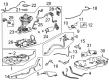
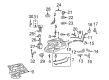
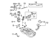
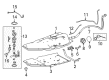
The Fuel Level Sensor in the Toyota Highlander cars is used to notify drivers the amount of fuel that is available in the tank. These electronic devices are constructed to be able to measure fuel level especially when exposed to high temperatures and this make the completion of the information required to be quick. Normally mounted inside the fuel tank, float, actuating rod and resistor are the main parts of the unit that pass signals on to the fuel gauge for interpretation. It is suggested that when there are problems with the fuel level sensor, then it is prime to consult the servicing of a professional. Normal operation of the sensors allows refueling alerts to be given as well as avoid circumstances like the car diary showing a 'full tank' for a longer period after subsequent refueling.
Toyota Highlander Fuel Level Sensor Parts and Q&A
- Q: How to install the Fuel Level Sensor assembly and related components on Toyota Highlander?A:You must mount the fuel level sensor gauge assembly by guiding it onto the claw and then put in the fuel suction tube assembly with the pump and gauge. The cable must connect to the negative terminal while checking for fuel leakage and then you must remove this cable from the negative terminal. After installing the rear floor service hole cover position and installing the deck trim side panel assembly LH you should connect the rear No. 1 seat outer belt assembly LH. The LM front deck side trim cover follows the No. 2 deck side trim hook alongside the rope hook assembly upon the LH side installation. First install the rear deck trim cover that needs no remote folding function or the reclining remote control lever bezel LH if remote folding is needed. Next install the rear power outlet socket cover and rear power point socket assembly. Begin by fixing the rear combination light service cover LH which can also include the side trim cover LH (if there is no rear seat entertainment system) or power outlet socket bezel (if there is a rear seat entertainment system). Afterward, attach the deck side trim LH and its corresponding cover LH. The necessary procedure includes installing the rear floor finish plate while also putting in the rear No. 2 seat assembly (with rear No. 2 seat) and connecting the rear seat lap type belt assembly LH and RH (with rear No. 2 seat). The installation process requires positioning of the rear No. 2 seat inner belt assembly followed by the rear deck floor box with no rear No. 2 seat and then placing the deck floor board assembly also with no rear No. 2 seat. Fasten the rear mat alongside the deck floor board assembly (with rear No. 2 seat) followed by installation of the deck side trim box LH, rear seat side cover LH (with rear No. 2 seat), deck side trim box RH, jack carrier assembly, jack assembly and jack carrier cushion. The assembly process requires installing the jack carrier support together with the rear seat side cover RH (with rear No. 2 seat) and the rear No. 1 floor board (without rear No. 2 seat) and the tonneau cover assembly (with tonneau cover) along with the No. 2 deck board sub-assembly, No. 3 deck board sub-assembly, and deck board assembly. Install the rear door opening trim Weather Strip LH as well as the rear door scuff plate LH and the rear No. 1 seat assembly RH with its connectable rear No. 1 seat lock cable assembly (that features remote folding ability). The assembly of rear No. 1 seat adjuster (for right side) requires completion before moving on to install the rear seat leg side cover RH and related components including rear inner track bracket cover RH, rear outer track bracket cover RH and seat track bracket cover RH and finally the rear seat headrest (for right side). The process should be repeated for the rear No. 1 seat assembly LH by connecting the rear No. 1 seat lock cable assembly (with remote folding function) and by checking the rear seat slide adjuster lock (for LH side). Install the rear seat leg side cover LH as well as the rear inner seat track bracket cover LH, rear outer track bracket cover LH, seat track bracket cover LH then position the rear seat headrest assembly (for LH side) before placing the rear center seat assembly. After reconnecting the cable to the negative terminal inspect the SRS warning light.
- Q: How to remove the Fuel Level Sensor assembly on Toyota Highlander?A:One must begin the fuel level sensor assembly removal by uninstalling the fuel suction tube assembly with pump and gauge as a complete unit. Disengage the connector before taking out the fuel level sensor from its location on the fuel suction tube.


Related Toyota Highlander Parts
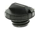 Toyota Highlander Gas Cap
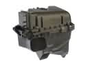 Toyota Highlander Air Filter Box
 Toyota Highlander Fuel Filter
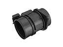 Toyota Highlander Mass Air Flow Sensor
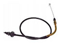 Toyota Highlander Accelerator Cable
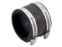 Toyota Highlander Air Intake Coupling
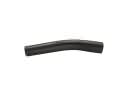 Toyota Highlander Fuel Filler Hose
 Toyota Highlander Fuel Pressure Regulator
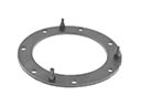 Toyota Highlander Fuel Pump Gasket
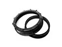 Toyota Highlander Fuel Pump Seal
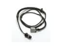 Toyota Highlander Fuel Pump Wiring Harness
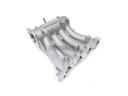 Toyota Highlander Intake Manifold