×
ToyotaParts- Hello
- Login or Register
- Quick Links
- Live Chat
- Track Order
- Parts Availability
- RMA
- Help Center
- Contact Us
- Shop for
- Toyota Parts
- Scion Parts
My Garage
My Account
Cart
OEM 2011 Toyota Venza Rear Crossmember
Rear Suspension Crossmember- Select Vehicle by Model
- Select Vehicle by VIN
Select Vehicle by Model
orMake
Model
Year
Select Vehicle by VIN
For the most accurate results, select vehicle by your VIN (Vehicle Identification Number).
2 Rear Crossmembers found

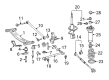
2011 Toyota Venza Suspension Crossmember, Rear
Part Number: 51206-06103$668.96 MSRP: $980.37You Save: $311.41 (32%)Ships in 1-3 Business DaysProduct Specifications- Other Name: Member Sub-Assembly, Rear; Suspension Subframe Crossmember, Rear; Crossmember; Member Sub-Assembly, Rear Suspension
- Position: Rear
- Replaces: 51206-06100, 51206-0E030, 51206-06102, 51206-06051, 51206-06101, 51206-06050
- Part Name Code: 51206A
- Item Weight: 19.10 Pounds
- Item Dimensions: 48.5 x 27.1 x 13.0 inches
- Condition: New
- Fitment Type: Direct Replacement
- SKU: 51206-06103
- Warranty: This genuine part is guaranteed by Toyota's factory warranty.

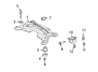 Product Specifications
- Other Name: Member Sub-Assembly, Rear; Suspension Subframe Crossmember, Rear; Member Sub-Assembly, Rear Suspension
- Position: Rear
- Replaces: 51206-0T020
- Part Name Code: 51206A
- Condition: New
- Fitment Type: Direct Replacement
- SKU: 51206-0T021
- Warranty: This genuine part is guaranteed by Toyota's factory warranty.
2011 Toyota Venza Rear Crossmember
Looking for affordable OEM 2011 Toyota Venza Rear Crossmember? Explore our comprehensive catalogue of genuine 2011 Toyota Venza Rear Crossmember. All our parts are covered by the manufacturer's warranty. Plus, our straightforward return policy and speedy delivery service ensure an unparalleled shopping experience. We look forward to your visit!
2011 Toyota Venza Rear Crossmember Parts Q&A
- Q: How to install the Rear Crossmember on 2011 Toyota Venza?A: The installation of AWD rear suspension member begins with stud bolt attachment on the LH side by using Special Service Tool: 09817-33190 and a 21 mm socket wrench to torque the bolt to 180 Nm (1839 kgf-cm, 133 ft-lbf). The same process must be performed on the RH side. Position the rear No. 2 body mounting bracket sub-assembly LH with two bolts (A) and one bolt (B) at their correct positions before interrupting the same process with the RH side. Install new rear suspension member body mounting front cushions for both the LH and RH sides after checking the installation direction. Proceed by using Special Service Tool: 09830-01010, 09830-10010, 09830-01020, 09830-01030, and 09830-01060 to verify the suspension member sub-assembly clearance from the cushions before applying grease to the center bolt threads. Repeat this for the RH side. Install the rear suspension member body mounting rear cushion for the LH side using Special Service Tools: 09515-21010 combined with 09830-36010 while checking for complete absence of clearance and lubricating the center bolt threads. After completing the RH installation place rear No. 1 differential mount cushion and rear No. 2 differential mount cushion before fully tightening the rear differential carrier assembly with differential support. After securing the rear differential carrier assembly with differential support install both rear suspension member body mounting rear cushions using 09515-21010 and 09830-36010. Finish tightening the differential carrier assembly with a full range torque. Before the final tightening of the bolt, users must first embed it into its specified position with 7 degrees 36' (7.6 degrees) at 49.7 mm (1.96 in.). Full bolt torque must reach 80 Nm (816 kgf-cm, 59 ft-lbf). Repeat for the RH side. Install the rear suspension member with a jack and several blocks positioned under it before raising it and setting the member in place with specified mount and stopper hardware. Tighten both nuts (A) to 115 Nm (1173 kgf-cm, 85 ft-lbf). Fully tighten the rear No. 2 body mounting bracket sub-assembly LH through light rear suspension member cushion settling while tightening all three bolts to 90 Nm (918 kgf-cm, 66 ft-lbf). Do the same for the RH side. Apply torque of 96 Nm (979 kgf-cm, 71 ft-lbf) when using 09961-00950 Special Service Tool but only 71 Nm (724 kgf-cm, 52 ft-lbf) with the tool under conditions where the torque wrench fulcrum length is 425 mm (1.39 ft.) and the tool remains parallel to the wrench. Six clamps should be attached before connecting the connector and hose to the frame wire while avoiding wire twisting. First install the non-twisted No. 3 floor wire while going ahead to set and install the snap rings along with rear drive shaft assemblies on both the left-hand side and right-hand side. Differential oil addition should be followed by installing the differential carrier cover plug. Link and temporarily secure both sides with their rear No. 1 suspension arm assemblies. For both sides install the rear strut rod assemblies followed by the rear height control sensor sub-assembly and the No. 3 parking brake cable assembly while tightening to the specified torque values. Apply the same steps to install the No. 2 parking brake cable assembly. Secure the rear axle shaft nuts and then fasten the rear speed sensors while avoiding wire twisting and protecting both the sensor tip and hole from foreign material entry. Install the No. 1 floor under cover while temporarily and finally tightening the propeller with center bearing shaft assembly and inspecting and adjusting transfer oil and installing the center exhaust pipe assembly. After installing both rear wheels at 103 Nm (1050 kgf-cm, 76 ft-lbf) torque you must stabilize the suspension and fully tighten the rear No. 2 suspension arm assemblies prior to inspecting and adjusting wheel alignment and testing speed sensors and the height control sensor and performing headlight aiming adjustments.
Related 2011 Toyota Venza Parts
 2011 Toyota Venza Shock Absorber
 2011 Toyota Venza Coil Spring Insulator
 2011 Toyota Venza Coil Springs
 2011 Toyota Venza Control Arm
 2011 Toyota Venza Crossmember Bushing
 2011 Toyota Venza Lateral Link
 2011 Toyota Venza Shock And Strut Mount
 2011 Toyota Venza Steering Knuckle
 2011 Toyota Venza Sway Bar Bracket
 2011 Toyota Venza Sway Bar Bushing
 2011 Toyota Venza Sway Bar Kit
 2011 Toyota Venza Sway Bar Link