×
ToyotaParts- Hello
- Login or Register
- Quick Links
- Live Chat
- Track Order
- Parts Availability
- RMA
- Help Center
- Contact Us
- Shop for
- Toyota Parts
- Scion Parts
My Garage
My Account
Cart
OEM 2010 Scion xB Cylinder Head Gasket
Engine Cylinder Head Gasket- Select Vehicle by Model
- Select Vehicle by VIN
Select Vehicle by Model
orMake
Model
Year
Select Vehicle by VIN
For the most accurate results, select vehicle by your VIN (Vehicle Identification Number).
1 Cylinder Head Gasket found


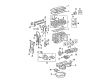
2010 Scion xB Head Gasket
Part Number: 11115-28040$74.52 MSRP: $104.61You Save: $30.09 (29%)Ships in 1-3 Business DaysProduct Specifications- Other Name: Gasket, Cylinder Head; Engine Cylinder Head Gasket; Cylinder Head Gasket; Engine Gasket Set
- Replaces: 11115-28011, 11115-28010, 11115-28012, 11115-28013
- Part Name Code: 11115
- Item Weight: 0.70 Pounds
- Item Dimensions: 18.9 x 13.8 x 3.2 inches
- Condition: New
- Fitment Type: Direct Replacement
- SKU: 11115-28040
- Warranty: This genuine part is guaranteed by Toyota's factory warranty.
2010 Scion xB Cylinder Head Gasket
Looking for affordable OEM 2010 Scion xB Cylinder Head Gasket? Explore our comprehensive catalogue of genuine 2010 Scion xB Cylinder Head Gasket. All our parts are covered by the manufacturer's warranty. Plus, our straightforward return policy and speedy delivery service ensure an unparalleled shopping experience. We look forward to your visit!
2010 Scion xB Cylinder Head Gasket Parts Q&A
- Q: How to install the cylinder head gasket on 2010 Scion xB?A: The 2AZ-FE engine requires positioning a fresh gasket on the cylinder block surface where the Lot No. stamp points upward so remove all oil residue from the contact surface while carefully following installation direction. Cylinder heads should be set on gasket pads with care before installing cylinder head bolts while providing engine oil to thread areas and head bottoms. Tighten the 10 cylinder head set bolts and plate washers in a specified order using a 10 mm bi-hexagon wrench until they reach 70 Nm (714 kgf-cm, 52 ft-lbf) torque, apply paint marks on each bolt front surface, then continue torquing them by an additional 90 degrees while confirming the marks form proper 90 degrees angles relative to bolt fronts. First install the No. 1 and No. 2 camshaft bearings before adding the camshafts and connecting the heater water hoses both for inlet and outlet as well as the inlet radiator hose. Connect all sensors as well as the heater water inlet hose by affixing the ground cable with 8.4 Nm (86 kgf-cm, 74 in-lbf) torque. Position the crankshaft key horizontally to the left and fit the No. 2 chain sub-assembly while aligning its yellow mark links with timing marks then tighten the oil pump drive shaft sprocket. First insert the damper spring into the adjusting hole followed by chain tensioner plate installation at 12 Nm (122 kgf-cm, 9 ft-lbf) torque but maintain stable position of the oil pump drive shaft sprocket with a 4 mm diameter rod before securing the nut to 30 Nm (301 kgf-cm, 22 ft-lbf). The crankshaft timing gear or sprocket together with the No. 1 chain vibration damper should be installed with 9.0 Nm (92 kgf-cm, 80 in-lbf) torque while the chain sub-assembly gets installed with the No. 1 cylinder set to TDC/compression after timing marks alignment. Before tightening the chain tensioner slipper install it with 19 Nm (194 kgf-cm, 14 ft-lbf) torque, then torque the timing chain guide to 9.0 Nm (92 kgf-cm, 80 in-lbf). The timing chain or belt cover sub-assembly requires installation before 3 minutes from packing application while maintaining forward-facing orientation of the "F" mark on the No. 1 crankshaft position sensor plate. First measure and then apply proper torque values to fix all timing chain cover bolts before installing the stud bolt for the V-ribbed belt tensioner (22 Nm, 219 kgf-cm, 16 ft-lbf) followed by installing the No. 1 chain tensioner assembly with accurate plunger placement. The V-ribbed belt tensioner assembly needs installation with a torque of 60 Nm (607 kgf-cm, 44 ft-lbf) after which the transverse engine mounting bracket requires a torque of 55 Nm (561 kgf-cm, 41 ft-lbf). Use Special Service Tool: 09213-54015 91651-60855 to fix the crankshaft pulley before securing the bolt at 180 Nm (1835 kgf-cm, 133 ft-lbf). After applying a continuous seal packing bead to the oil pan sub-assembly install it while tightening bolts and nuts in sequence to 9.0 Nm (92 kgf-cm, 80 in-lbf). Finally, install the crankshaft position sensor, idler pulley sub-assembly, engine mounting insulator sub-assembly RH, front engine mounting insulator, exhaust manifold converter, heat insulator, manifold stays, intake manifold, camshaft timing oil control valve assembly, fuel delivery pipe, and connect the fuel main tube, ensuring to torque all components as specified, and complete the installation by connecting the negative battery terminal and adding engine oil and coolant while inspecting for leaks.
Related 2010 Scion xB Parts
 2010 Scion xB Oil Filter
 2010 Scion xB Oil Pan
 2010 Scion xB Timing Chain
 2010 Scion xB Crankshaft Thrust Washer Set
 2010 Scion xB Dipstick Tube
 2010 Scion xB Drain Plug Washer
 2010 Scion xB Exhaust Valve
 2010 Scion xB Intake Valve
 2010 Scion xB Oil Pump
 2010 Scion xB Piston Ring Set
 2010 Scion xB Timing Chain Guide
 2010 Scion xB Timing Cover