×
ToyotaParts- Hello
- Login or Register
- Quick Links
- Live Chat
- Track Order
- Parts Availability
- RMA
- Help Center
- Contact Us
- Shop for
- Toyota Parts
- Scion Parts
My Garage
My Account
Cart
OEM 2009 Toyota Matrix Blend Door Actuator
Air Blend Door Actuator- Select Vehicle by Model
- Select Vehicle by VIN
Select Vehicle by Model
orMake
Model
Year
Select Vehicle by VIN
For the most accurate results, select vehicle by your VIN (Vehicle Identification Number).
1 Blend Door Actuator found

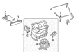
2009 Toyota Matrix Servo
Part Number: 87106-02210$135.82 MSRP: $192.27You Save: $56.45 (30%)Ships in 1-3 Business DaysProduct Specifications- Other Name: Servo Sub-Assembly, Damper; HVAC Air Control Motor; Air Inlet/Heater Blend Door Actuator; Servo Sub-Assembly, Damper(For Recirculation)
- Manufacturer Note: AIR CONDITIONER-MANUAL
- Replaces: 87106-42130, 87106-02430
- Item Weight: 1.40 Pounds
- Item Dimensions: 6.1 x 4.6 x 3.4 inches
- Condition: New
- Fitment Type: Direct Replacement
- SKU: 87106-02210
- Warranty: This genuine part is guaranteed by Toyota's factory warranty.
2009 Toyota Matrix Blend Door Actuator
Looking for affordable OEM 2009 Toyota Matrix Blend Door Actuator? Explore our comprehensive catalogue of genuine 2009 Toyota Matrix Blend Door Actuator. All our parts are covered by the manufacturer's warranty. Plus, our straightforward return policy and speedy delivery service ensure an unparalleled shopping experience. We look forward to your visit!
2009 Toyota Matrix Blend Door Actuator Parts Q&A
- Q: What is the role of the Blend Door Actuator in the heating and air conditioning system on 2009 Toyota Matrix?A: The air door actuator serves as a heating and air conditioning system component which performs under the name air inlet control servo motor. The air door actuator controls cabin airflow entry through its adjustments of air door positions. Maintaining the proper condition of an air door actuator necessitates professional service work for guaranteeing peak performance of vehicle climate control systems.
Related 2009 Toyota Matrix Parts
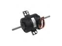 2009 Toyota Matrix Blower Motor
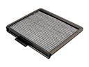 2009 Toyota Matrix Cabin Air Filter
 2009 Toyota Matrix A/C Accumulator
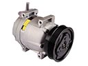 2009 Toyota Matrix A/C Compressor
 2009 Toyota Matrix A/C Condenser
 2009 Toyota Matrix A/C Expansion Valve
 2009 Toyota Matrix A/C Hose
 2009 Toyota Matrix Ambient Temperature Sensor
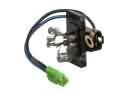 2009 Toyota Matrix Blower Motor Resistor
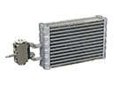 2009 Toyota Matrix Evaporator
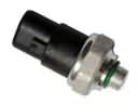 2009 Toyota Matrix HVAC Pressure Switch
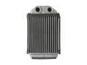 2009 Toyota Matrix Heater Core