×
ToyotaParts- Hello
- Login or Register
- Quick Links
- Live Chat
- Track Order
- Parts Availability
- RMA
- Help Center
- Contact Us
- Shop for
- Toyota Parts
- Scion Parts
My Garage
My Account
Cart
OEM 2008 Toyota Sienna Fuel Pressure Regulator
Fuel Tank Pressure Regulator- Select Vehicle by Model
- Select Vehicle by VIN
Select Vehicle by Model
orMake
Model
Year
Select Vehicle by VIN
For the most accurate results, select vehicle by your VIN (Vehicle Identification Number).
1 Fuel Pressure Regulator found


2008 Toyota Sienna Damper Assembly, Fuel Pressure Pulsation
Part Number: 23270-31140$111.14 MSRP: $156.01You Save: $44.87 (29%)Ships in 1-3 Business DaysProduct Specifications- Other Name: Fuel Pressure Damper; Fuel Pump Pulsator
- Replaces: 23270-31080, 23270-31010
- Part Name Code: 23270
- Item Weight: 0.50 Pounds
- Item Dimensions: 3.0 x 2.3 x 2.0 inches
- Condition: New
- Fitment Type: Direct Replacement
- SKU: 23270-31140
- Warranty: This genuine part is guaranteed by Toyota's factory warranty.
2008 Toyota Sienna Fuel Pressure Regulator
Looking for affordable OEM 2008 Toyota Sienna Fuel Pressure Regulator? Explore our comprehensive catalogue of genuine 2008 Toyota Sienna Fuel Pressure Regulator. All our parts are covered by the manufacturer's warranty. Plus, our straightforward return policy and speedy delivery service ensure an unparalleled shopping experience. We look forward to your visit!
2008 Toyota Sienna Fuel Pressure Regulator Parts Q&A
- Q: How to install the fuel pressure regulator and related components on 2008 Toyota Sienna?A: Begin the fuel pressure pulsation damper installation by applying spindle oil or gasoline to a new O-ring before installing it to the damper. You should install the fuel pressure pulsation damper onto the fuel delivery pipe by using the clip to fasten it. The installer should progress by putting together the intake air surge tank assembly and completing the installation of the air cleaner cap sub-assembly. The engine must receive coolant before you can put the cable onto the negative battery terminal. Maintenance personnel need to check for coolant leakage before installing the No. 1 engine under cover. A complete examination for fuel leaks must occur before the V-bank cover sub-assembly installation takes place. Together the aircraft must receive the cowl top panel sub-assembly outer front component followed by the No. 1 cowl top to cowl brace inner, windshield wiper motor and link assembly while receiving the front wiper arm LH and RH.
Related 2008 Toyota Sienna Parts
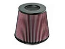 2008 Toyota Sienna Air Filter
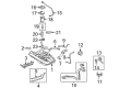
 2008 Toyota Sienna Fuel Tank
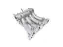 2008 Toyota Sienna Intake Manifold
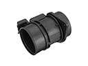 2008 Toyota Sienna Mass Air Flow Sensor
 2008 Toyota Sienna Air Duct
 2008 Toyota Sienna Air Intake Coupling
 2008 Toyota Sienna Fuel Filler Hose
 2008 Toyota Sienna Fuel Pump Seal
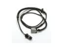 2008 Toyota Sienna Fuel Pump Wiring Harness
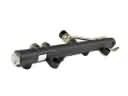 2008 Toyota Sienna Fuel Rail
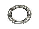 2008 Toyota Sienna Fuel Tank Lock Ring
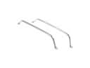 2008 Toyota Sienna Fuel Tank Strap