×
ToyotaParts- Hello
- Login or Register
- Quick Links
- Live Chat
- Track Order
- Parts Availability
- RMA
- Help Center
- Contact Us
- Shop for
- Toyota Parts
- Scion Parts
My Garage
My Account
Cart
OEM 2008 Toyota Prius Control Arm
Suspension Arm- Select Vehicle by Model
- Select Vehicle by VIN
Select Vehicle by Model
orMake
Model
Year
Select Vehicle by VIN
For the most accurate results, select vehicle by your VIN (Vehicle Identification Number).
2 Control Arms found


2008 Toyota Prius Lower Control Arm, Driver Side
Part Number: 48069-47040$136.84 MSRP: $193.71You Save: $56.87 (30%)Ships in 1-2 Business DaysProduct Specifications- Other Name: Arm Sub-Assembly, Suspension; Suspension Control Arm, Front Left; Control Arm Assembly; Arm Sub-Assembly, Front Suspension, Lower Driver Side; Control Arm
- Position: Lower Driver Side
- Replaces: 48069-47030
- Part Name Code: 48069
- Item Weight: 7.40 Pounds
- Item Dimensions: 16.6 x 7.2 x 18.3 inches
- Condition: New
- Fitment Type: Direct Replacement
- SKU: 48069-47040
- Warranty: This genuine part is guaranteed by Toyota's factory warranty.

2008 Toyota Prius Lower Control Arm, Passenger Side
Part Number: 48068-47040$136.84 MSRP: $193.71You Save: $56.87 (30%)Ships in 1-3 Business DaysProduct Specifications- Other Name: Arm Sub-Assembly, Suspension; Suspension Control Arm, Front Right; Control Arm Assembly; Arm Sub-Assembly, Front Suspension, Lower Passenger Side; Control Arm
- Position: Passenger Side
- Replaces: 48068-47030
- Part Name Code: 48068
- Item Weight: 7.20 Pounds
- Item Dimensions: 16.3 x 7.1 x 17.8 inches
- Condition: New
- Fitment Type: Direct Replacement
- SKU: 48068-47040
- Warranty: This genuine part is guaranteed by Toyota's factory warranty.
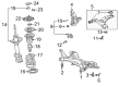
2008 Toyota Prius Control Arm
Looking for affordable OEM 2008 Toyota Prius Control Arm? Explore our comprehensive catalogue of genuine 2008 Toyota Prius Control Arm. All our parts are covered by the manufacturer's warranty. Plus, our straightforward return policy and speedy delivery service ensure an unparalleled shopping experience. We look forward to your visit!
2008 Toyota Prius Control Arm Parts Q&A
- Q: How to install the Control Arm in the front suspension on 2008 Toyota Prius?A: The first step to install the front suspension lower No. 1 arm requires the attachment of the front suspension lower No. 1 arm sub-assembly LH to the suspension crossmember using 2 bolts and a nut with temporary tightening. Start with installing the front suspension crossmember sub-assembly and afterward attach the front drive shaft assembly LH and RH. Continue installation by adding the front axle assemblies LH followed by RH while keeping the right-hand side procedure identical to left-hand side installation. Use a bolt and 2 nuts to fasten the front suspension lower No. 1 arm sub-assembly LH to the front lower ball joint while torquing them to 89 Nm (908 kgf-cm, 66 ft-lbf). The installation of front suspension lower No. 1 arm sub-assembly RH also needs to be performed. The stabilizer link assembly connects to the front shock absorber with coil spring through nuts torqued to 74 Nm (755 kgf-cm, 55 ft-lbf). A 6mm hexagon wrench holds the stud if the ball joint rotates with the nut. After fitting the front axle hub nuts LH and RH, install the No. 2 tie rod end sub-assembly and the No. 1 tie rod end sub-assembly. The RH side installation follows the same sequence of steps used for the LH side. Attach the front wheel followed by torquing it to 103 Nm (1,050 kgf-cm, 76 ft-lbf) before installing the front exhaust pipe assembly. The suspension should be stabilized by letting the vehicle drop then performing multiple bounce movements. Establish the steering sliding yoke assembly before you install the column hole cover sheet for reduction of noise. The finishing step involves tightening the 2 bolts of the front suspension lower No. 1 arm sub-assembly LH to 137 Nm (1,400 kgf-cm, 101 ft-lbf) while preventing the nut from rotating during the process before dropping the tires to the floor using a 4-post lift. A necessary check of front wheel alignment will follow.
Related 2008 Toyota Prius Parts
 2008 Toyota Prius Sway Bar Link
 2008 Toyota Prius Alignment Bolt
 2008 Toyota Prius Bump Stop
 2008 Toyota Prius Coil Spring Insulator
 2008 Toyota Prius Coil Springs
 2008 Toyota Prius Control Arm Bolt
 2008 Toyota Prius Front Cross-Member
 2008 Toyota Prius Shock And Strut Mount
 2008 Toyota Prius Shock and Strut Boot
 2008 Toyota Prius Steering Knuckle
 2008 Toyota Prius Strut Housing
 2008 Toyota Prius Sway Bar Bushing