My Garage
Cart

OEM 2008 Scion xB Cylinder Head Gasket

Engine Cylinder Head Gasket
  • Select Vehicle by Model
  • Select Vehicle by VIN
Select Vehicle by Model
Make
Model
Year
or
Select Vehicle by VIN
For the most accurate results, select vehicle by your VIN (Vehicle Identification Number).

1 Cylinder Head Gasket found

  • 2008 Scion xB Cylinder Head Gasket - 11115-28040
    2008 Scion xB Cylinder Head Gasket Diagram - 11115-28040
    View related parts

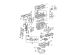
    2008 Scion xB Head Gasket

    Part Number: 11115-28040
    $71.56 MSRP: $100.45
    You Save: $28.89 (29%)
    Ships in 1-3 Business Days
    ADD TO CART
    Product Specifications
    • Other Name: Gasket, Cylinder Head; Engine Cylinder Head Gasket; Cylinder Head Gasket; Engine Gasket Set
    • Replaces: 11115-28011, 11115-28010, 11115-28012, 11115-28013
    • Part Name Code: 11115
    • Item Weight: 0.70 Pounds
    • Item Dimensions: 18.9 x 13.8 x 3.2 inches
    • Condition: New
    • Fitment Type: Direct Replacement
    • SKU: 11115-28040
    • Warranty: This genuine part is guaranteed by Toyota's factory warranty.
    More Info
    Fits the following 2008 Scion xB Submodels:
    • Base | 4 Cyl 2.4 L GAS

2008 Scion xB Cylinder Head Gasket

Looking for affordable OEM 2008 Scion xB Cylinder Head Gasket? Explore our comprehensive catalogue of genuine 2008 Scion xB Cylinder Head Gasket. All our parts are covered by the manufacturer's warranty. Plus, our straightforward return policy and speedy delivery service ensure an unparalleled shopping experience. We look forward to your visit!

2008 Scion xB Parts Questions & Experts Answers

  • Q: How to remove the cylinder head gasket on 2008 Scion xB?
    A: A proper procedure to extract the 2AZ-FE engine cylinder head gasket requires first discharging fuel system pressure before disconnecting the negative battery terminal cable along with a minimum 90-second wait period for Air Bag prevention. The hood needs to be taken off after the washer hose disconnect and hood bolt removal step. Initially detach the front right wheel followed by the No. 1 engine under cover and finally the rear engine under cover from the right side of the vehicle. The service starts with removing the No. 1 engine cover sub-assembly while draining engine coolant and oil and disassembling the center and front exhaust pipe assemblies. The procedure requires removal of windshield wiper arm cover followed by taking out both front wiper arm and blade assemblies together with the hood to cowl top seal and both cowl top ventilator louvers. Remove the items which include the front wiper motor and link and the outer cowl top panel together with the fan and generator V belt and the generator assembly. To begin disassembly it is necessary to undo bolts that secure the radiator reserve tank assembly before you remove air cleaner cap sub-assembly with hose together with throttle body assembly and ignition coil assembly and spark plug. Reverse the process by removing the cylinder head cover sub-assembly along with oil dipstick and its guide while keeping attention on the O-ring. Disconnect the fuel main tube while you remove the fuel delivery pipe sub-assembly together with the camshaft timing oil control valve assembly and intake manifold and intake manifold insulator. First disconnect the air-fuel ratio sensor connector before removing the exhaust manifold converter sub-assembly with No. 1 exhaust manifold heat insulator and the manifold stay and No. 2 manifold stay. Remove the right-hand engine mounting insulator sub-assembly while using caution toward the return tube then take out the front engine mounting insulator sub-assembly. The idler pulley sub-assembly should be removed first followed by the oil pan sub-assembly while installing new bolts onto the No. 1 and No. 2 engine hangers and torquing them to 38 Nm (387 kgf-cm, 28 ft-lbf). To set No. 1 cylinder at TDC/compression position start by placing the crankshaft pulley groove directly on the timing mark "0" of the timing chain cover. Then verify that both camshaft timing gear and sprocket marks align properly. Before proceeding with the operation uninstall the crankshaft pulley together with the No. 1 chain tensioner assembly and transverse engine mounting bracket and V-ribbed belt tensioner assembly. The work sequence for engine disassembly includes removing the crankshaft position sensor together with timing chain or belt cover assembly, No. 1 crankshaft sensor plate, timing chain guide and chain tensioner slipper and No. 1 chain vibration damper. Destroy the chain sub-assembly by turning the crankshaft 90 degrees counterclockwise to align the adjusting hole on the oil pump drive shaft sprocket with the groove on the oil pump. Secure the gear position using a 4 mm diameter bar before removing the nut, bolt, chain tensioner plate, spring, oil pump drive sprocket, oil pump drive shaft sprocket, and No. 2 chain. The removal of all necessary connections through insulator disconnection will allow separating the inlet radiator hose from the outlet heater water hose and inlet heater water hose as well as engine wire separation followed by ground cable bolt removal. To remove the No. 2 camshaft along with the camshaft followed by the No. 1 and No. 2 camshaft bearings and cylinder head sub-assembly operators should first evenly loose each of the ten cylinder head bolts and their corresponding plate washers pursuant to their specified ordering sequence before using proper force to separate the cylinder head from the cylinder block without causing damage to other components. The gasket for the cylinder head should also be extracted.

Related 2008 Scion xB Parts