×
ToyotaParts- Hello
- Login or Register
- Quick Links
- Live Chat
- Track Order
- Parts Availability
- RMA
- Help Center
- Contact Us
- Shop for
- Toyota Parts
- Scion Parts
My Garage
My Account
Cart
OEM 2007 Toyota Land Cruiser Wheel Hub
Wheel Axle Hub- Select Vehicle by Model
- Select Vehicle by VIN
Select Vehicle by Model
orMake
Model
Year
Select Vehicle by VIN
For the most accurate results, select vehicle by your VIN (Vehicle Identification Number).
1 Wheel Hub found


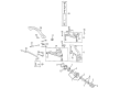
2007 Toyota Land Cruiser Hub Assembly, Front
Part Number: 43503-69035$368.52 MSRP: $540.07You Save: $171.55 (32%)Ships in 1 Business DayProduct Specifications- Other Name: Hub Sub-Assembly, Front Axle; Wheel Bearing and Hub Assembly, Front; Wheel Hub Repair Kit; Wheel Hub; Front Hub
- Position: Front
- Replaces: 43503-69015
- Item Weight: 1.40 Pounds
- Item Dimensions: 6.9 x 6.7 x 4.8 inches
- Condition: New
- SKU: 43503-69035
- Warranty: This genuine part is guaranteed by Toyota's factory warranty.
2007 Toyota Land Cruiser Wheel Hub
Looking for affordable OEM 2007 Toyota Land Cruiser Wheel Hub? Explore our comprehensive catalogue of genuine 2007 Toyota Land Cruiser Wheel Hub. All our parts are covered by the manufacturer's warranty. Plus, our straightforward return policy and speedy delivery service ensure an unparalleled shopping experience. We look forward to your visit!
2007 Toyota Land Cruiser Wheel Hub Parts Q&A
- Q: How to service and repair the front Wheel Hub on 2007 Toyota Land Cruiser?A: Perform on-vehicle inspections by separating the front wheel, front disc brake cylinder and front disc and check the wheel hub backlash with a dial indicator; replace the bearing when the measurement exceeds 0.05 mm (0.0020 inch). Check the wheel hub deviation using the same procedure before proceeding to replace the bearing if needed. The front wheel should be removed first followed by disconnecting the flexible hose from the steering knuckle then removing the brake cylinder assembly after removing the bolts and washers. Operation starts with supporting the brake cylinder before removing each piece from the front axle outer shaft flange using a sequential order of grease cap removal followed by snap ring removal and finally 6 nuts and washers off. Once removed temporarily install those washers to prevent thread damage. You should use a brass bar and hammer to tap on bolt heads in order to remove nuts and cone washers from the front axle. After removing the bolts and washers, remove the flange and gasket. The removal process for the wheel hub with disc requires unlocking the lock washer followed by using SST 09607-60020 to separate the lock nut and adjusting nut while carefully protecting the ABS speed sensor rotor and oil seal. Proceed with removing the wheel hub with disc and the claw washer and bearing. The disassembly procedure begins by pulling out the oil seal to free the bearing from the wheel hub. A brass bar with hammer allows technicians to tap out both bearing races which enables an inspection for wear or damage in the bearing components. Place the wheel hub and disc inside a soft jaw vise at a proper angle before marking their corresponding positions while removing the 5 bolts to separate them. Medium-sized bolts should be torqued to 74 Nm (750 kgf-cm, 54 ft. lbs.) to connect the wheel hub with the disc while maintaining their matchmarks alignment on the vise. Install the new outer and inner bearing outer races with SST 09950-60020 (09951-00730) and 09950-70010 (09951-07100) before filling in MP grease to the extent that it oozes out from the wheel hub bearing. Following step-by-step, place MP grease inside the wheel hub then insert the inner bearing while using SST 09950-60020 (09951-01030), 09951-07100 to push in the new oil seal ensuring the lip gets coated with MP grease. The installation process starts by positioning the wheel hub with disc on the steering knuckle and subsequently inserting the outer bearing followed by the claw washer. Adjust preload by tightening the adjusting nut with SST 09607-60020 to 59 Nm (600 kgf-cm, 43 ft. lbs.) and execute several turns on the wheel hub followed by an adjustment until the nut becomes hand-rotatable before the re-application of torque to 4.3 to 6.5 Nm (44 to 66 kgf-cm, 38 to 57 inch lbs.) with a loose-ness check. Finally, lock the Install a new lock washer followed by a new lock nut then adjust the torque on the lock nut to 64 Nm (650 kgf-cm, 47 ft. lbs.) while confirming smooth rotation and rechecking preload. Afterward, both the lock washer and new lock nut must stay in place through the bending of lock washer teeth. Security of the lock nut requires bending lock washer teeth. To install the wheel hub with the flange you must first set the snap ring clearance to under 0.2 mm (0.008 inch). Then apply 6 cone washers, 6 washers, and 6 new nuts which require a torque of 33 Nm (335 kgf-cm, 24 ft. lbs.) before fitting the new snap ring and grease cap. Complete the operation by installing the brake caliper with 2 washers and bolts reaching 123 Nm (1,250 kgf-cm, 91 ft. lbs.), connecting the flexible hose and bolt to the steering knuckle at 28 Nm (290 kgf-cm, 21 ft. lbs.) and installing the front wheel at 131 Nm (1,340 kgf-cm, 97 ft. lbs.) while performing an ABS speed sensor signal check.
Related 2007 Toyota Land Cruiser Parts
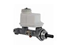 2007 Toyota Land Cruiser Brake Master Cylinder
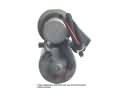 2007 Toyota Land Cruiser ABS Pump And Motor Assembly
 2007 Toyota Land Cruiser Brake Caliper Piston
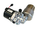 2007 Toyota Land Cruiser Brake Fluid Pump
 2007 Toyota Land Cruiser Brake Line
 2007 Toyota Land Cruiser Brake Master Cylinder Reservoir
 2007 Toyota Land Cruiser Brake Pad Set
 2007 Toyota Land Cruiser Brake Shoe Set
 2007 Toyota Land Cruiser Hydraulic Hose
 2007 Toyota Land Cruiser Parking Brake Shoe
 2007 Toyota Land Cruiser Spindle Nut
 2007 Toyota Land Cruiser Wheel Cylinder Repair Kit