×
ToyotaParts- Hello
- Login or Register
- Quick Links
- Live Chat
- Track Order
- Parts Availability
- RMA
- Help Center
- Contact Us
- Shop for
- Toyota Parts
- Scion Parts
My Garage
My Account
Cart
OEM 2007 Toyota FJ Cruiser Canister Purge Valve
Vapor Canister Purge Valve EVAP- Select Vehicle by Model
- Select Vehicle by VIN
Select Vehicle by Model
orMake
Model
Year
Select Vehicle by VIN
For the most accurate results, select vehicle by your VIN (Vehicle Identification Number).
1 Canister Purge Valve found


2007 Toyota FJ Cruiser Purge Solenoid, Driver Side
Part Number: 90910-AC001$84.24 MSRP: $118.25You Save: $34.01 (29%)Ships in 1 Business DayProduct Specifications- Other Name: Valve, Duty Vacuum Switching; EGR Vacuum Delay Valve; Vapor Canister Purge Solenoid; Air Injection Check Valve; Vacuum Switch; Vacuum Valve; Air Switch Valve; Vacuum Delay Valve
- Manufacturer Note: MEXICO SPEC
- Position: Driver Side
- Replaces: 90910-12262
- Part Name Code: 17650G
- Item Weight: 0.50 Pounds
- Item Dimensions: 3.4 x 3.4 x 2.8 inches
- Condition: New
- Fitment Type: Direct Replacement
- SKU: 90910-AC001
- Warranty: This genuine part is guaranteed by Toyota's factory warranty.
2007 Toyota FJ Cruiser Canister Purge Valve
Looking for affordable OEM 2007 Toyota FJ Cruiser Canister Purge Valve? Explore our comprehensive catalogue of genuine 2007 Toyota FJ Cruiser Canister Purge Valve. All our parts are covered by the manufacturer's warranty. Plus, our straightforward return policy and speedy delivery service ensure an unparalleled shopping experience. We look forward to your visit!
2007 Toyota FJ Cruiser Canister Purge Valve Parts Q&A
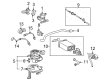
- Q: How to service and repair the Canister Purge Valve on 2007 Toyota FJ Cruiser?A: The first step when servicing or repairing the Canister Purge Valve requires disconnecting the negative battery cable. The first repair step includes disconnecting the V-bank cover as well as the duty vacuum switching valve by conducting connector removal and fuel vapor feed hose detachment and valve separation from the intake air surge tank followed by hose removal of the valve. Before installation attach the vacuum switching valve hose then secure the device using a bolt tightened to 9.0 N.m (92 kgf.cm, 80 in.lbf) and finally connect the vapor feed hose and the connector. Toward the conclusion attach the V-bank cover together with connecting the cable to the negative battery terminal using 3.9 N.m (40 kgf.cm, 35 in.lbf) of torque.
Related 2007 Toyota FJ Cruiser Parts
 2007 Toyota FJ Cruiser Catalytic Converter
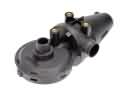 2007 Toyota FJ Cruiser PCV Valve
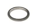 2007 Toyota FJ Cruiser Exhaust Flange Gasket
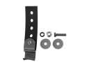 2007 Toyota FJ Cruiser Exhaust Hanger
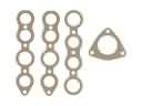 2007 Toyota FJ Cruiser Exhaust Manifold
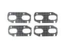 2007 Toyota FJ Cruiser Exhaust Manifold Gasket
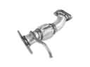 2007 Toyota FJ Cruiser Exhaust Pipe
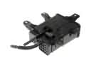 2007 Toyota FJ Cruiser Vapor Canister