×
ToyotaParts- Hello
- Login or Register
- Quick Links
- Live Chat
- Track Order
- Parts Availability
- RMA
- Help Center
- Contact Us
- Shop for
- Toyota Parts
- Scion Parts
My Garage
My Account
Cart
OEM 2006 Toyota Tundra Alternator
Generator- Select Vehicle by Model
- Select Vehicle by VIN
Select Vehicle by Model
orMake
Model
Year
Select Vehicle by VIN
For the most accurate results, select vehicle by your VIN (Vehicle Identification Number).
3 Alternators found


2006 Toyota Tundra Alternator
Part Number: 27060-0F040-84$222.61 MSRP: $296.45You Save: $73.84 (25%)Ships in 1-3 Business DaysProduct Specifications- Other Name: Reman Alternator 2Uz
- Replaces: 27060-0F040
- Item Weight: 14.60 Pounds
- Item Dimensions: 13.1 x 10.6 x 8.8 inches
- Condition: New
- SKU: 27060-0F040-84
- Warranty: This genuine part is guaranteed by Toyota's factory warranty.

2006 Toyota Tundra Alternator
Part Number: 27060-0F060-84$280.86 MSRP: $399.56You Save: $118.70 (30%)Ships in 1-3 Business DaysProduct Specifications- Other Name: Reman Alternator
- Replaces: 27060-0F060
- Item Weight: 15.10 Pounds
- Item Dimensions: 13.5 x 10.8 x 8.8 inches
- Condition: New
- SKU: 27060-0F060-84
- Warranty: This genuine part is guaranteed by Toyota's factory warranty.

2006 Toyota Tundra Alternator
Part Number: 27060-0P030-84$194.42 MSRP: $258.64You Save: $64.22 (25%)Ships in 1-3 Business DaysProduct Specifications- Other Name: Reman Alternator 1Gr
- Replaces: 27060-0P030
- Item Weight: 13.80 Pounds
- Item Dimensions: 13.0 x 10.6 x 8.8 inches
- Condition: New
- SKU: 27060-0P030-84
- Warranty: This genuine part is guaranteed by Toyota's factory warranty.
2006 Toyota Tundra Alternator
Looking for affordable OEM 2006 Toyota Tundra Alternator? Explore our comprehensive catalogue of genuine 2006 Toyota Tundra Alternator. All our parts are covered by the manufacturer's warranty. Plus, our straightforward return policy and speedy delivery service ensure an unparalleled shopping experience. We look forward to your visit!
2006 Toyota Tundra Alternator Parts Q&A
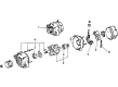
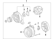
- Q: How to service and repair the alternator on 2006 Toyota Tundra?A: A proper start to servicing and repairing the alternator needs the removal of four bolts from the V-bank cover and engine under cover. The first step includes removing the V belt that connects the fan to the generator and the battery from its position. Begin generator removal by disconnecting the wire harness and then removing the bolt as well as the wire harness stay. Then disconnect the connector from the generator before removing the terminal cap and nut. Next disconnect the wire harness from terminal B. Start by taking away two bolts and the wire harness clamp bracket from the generator assembly followed by removing the two bolts that attach the generator. The generator installation process requires users to first secure the 2 bolts at 43 N.m (438 kgf.cm, 32 ft.lbf) while installing the generator. To complete the procedure first connect the wire harness to terminal B and install its nut using a torque of 9.8 N.m (100 kgf.cm, 7 ft.lbf) while the generator assembly requires connection of the connector. Last, install the wire harness stay with the bolt tightened to 8.0 N.m (82 kgf.cm, 71 in.lbf). The installation process requires a battery reinstallation followed by placing the fan and then setting the generator V belt. The engine under cover sub-assembly No.1 needs installation with 4 bolts achieving a torque setting of 29 N.m (296 kgf.cm, 21 ft.lbf) before installing the V-bank cover using 2 nuts at 9.8 N.m (100 kgf.cm, 87 in.lbf).
Related 2006 Toyota Tundra Parts
 2006 Toyota Tundra Battery Terminal
 2006 Toyota Tundra Starter Solenoid
 2006 Toyota Tundra Alternator Bearing
 2006 Toyota Tundra Alternator Brush
 2006 Toyota Tundra Alternator Case Kit
 2006 Toyota Tundra Alternator Pulley
 2006 Toyota Tundra Armature
 2006 Toyota Tundra Battery Tray
 2006 Toyota Tundra Car Batteries
 2006 Toyota Tundra Starter Brush
 2006 Toyota Tundra Starter Drive Gear
 2006 Toyota Tundra Starter Motor