×
ToyotaParts- Hello
- Login or Register
- Quick Links
- Live Chat
- Track Order
- Parts Availability
- RMA
- Help Center
- Contact Us
- Shop for
- Toyota Parts
- Scion Parts
My Garage
My Account
Cart
OEM 2005 Toyota Land Cruiser Brake Master Cylinder
- Select Vehicle by Model
- Select Vehicle by VIN
Select Vehicle by Model
orMake
Model
Year
Select Vehicle by VIN
For the most accurate results, select vehicle by your VIN (Vehicle Identification Number).
1 Brake Master Cylinder found


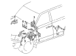
2005 Toyota Land Cruiser Brake Booster Assembly, W/Master Cylinder
Part Number: 47050-60043$1369.03 MSRP: $2006.33You Save: $637.30 (32%)Ships in 1-3 Business DaysProduct Specifications- Other Name: Cylinder Assembly, Brake; ABS Pump And Motor Assembly; Brake Master Cylinder; ABS Control Module
- Part Name Code: 47210L
- Item Weight: 32.10 Pounds
- Item Dimensions: 17.1 x 13.7 x 12.8 inches
- Condition: New
- Fitment Type: Direct Replacement
- SKU: 47050-60043
- Warranty: This genuine part is guaranteed by Toyota's factory warranty.
2005 Toyota Land Cruiser Brake Master Cylinder
Looking for affordable OEM 2005 Toyota Land Cruiser Brake Master Cylinder? Explore our comprehensive catalogue of genuine 2005 Toyota Land Cruiser Brake Master Cylinder. All our parts are covered by the manufacturer's warranty. Plus, our straightforward return policy and speedy delivery service ensure an unparalleled shopping experience. We look forward to your visit!
2005 Toyota Land Cruiser Brake Master Cylinder Parts Q&A
- Q: How to Remove and Install the Brake Master Cylinder and Hydraulic Brake Booster Assembly on 2005 Toyota Land Cruiser?A: Begin the work only after turning off the ignition switch and performing more than 40 brake pedal depressions. A decrease of pressure in the power supply system causes the reaction force to decrease while the stroke duration increases. You must not switch ON the ignition and need to keep out of tubular bite actuator No. 1 deformation while performing the work. Start by extracting fluid through the syringe while actively preventing brake fluid contact on painted surfaces and immediately cleaning this contact if it occurs. The necessary components include the scuff plate followed by cowl side trim and lower No. 1 panel and LH lower panel combined with No. 2 heater to register duct. Users should dismantle the 2 existing ABS or ABS & TRAC & VSC ECU nuts then install them using 5.0 Nm (51 kgf-cm, 44 inch lbs.) of torque. Use the Special Service Tool: 09023-00101 to disconnect 4 connectors and the 3 brake lines on vehicles with ABS before installing them with a torque value of 15 Nm (155 kgf-cm, 11 ft. lbs.). When servicing ABS and TRAC and VSC components you must disconnect 5 connectors while also using the same tool to detach the 4 brake lines according to specified torque values. The next step involves removing the clip and clevis pin followed by removal of the hydraulic brake booster assembly through unfastening the 4 booster installation nuts with a torque of 15 Nm (155 kgf-cm, 11 ft. lbs.). During this phase, the booster assembly and gasket should be extracted. The installation process follows the exact opposite steps of removal thus starting with brake fluid addition to the reservoir before proceeding to brake system bleeding and leak detection.
Related 2005 Toyota Land Cruiser Parts
 2005 Toyota Land Cruiser Speed Sensor
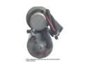 2005 Toyota Land Cruiser ABS Pump And Motor Assembly
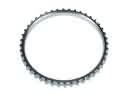 2005 Toyota Land Cruiser ABS Reluctor Ring
 2005 Toyota Land Cruiser Brake Caliper Bracket
 2005 Toyota Land Cruiser Brake Caliper Piston
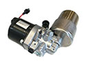 2005 Toyota Land Cruiser Brake Fluid Pump
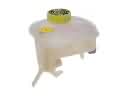 2005 Toyota Land Cruiser Brake Master Cylinder Reservoir
 2005 Toyota Land Cruiser Brake Pad Set
 2005 Toyota Land Cruiser Brake Shoe Set
 2005 Toyota Land Cruiser Parking Brake Shoe
 2005 Toyota Land Cruiser Wheel Cylinder
 2005 Toyota Land Cruiser Wheel Hub