×
ToyotaParts- Hello
- Login or Register
- Quick Links
- Live Chat
- Track Order
- Parts Availability
- RMA
- Help Center
- Contact Us
- Shop for
- Toyota Parts
- Scion Parts
My Garage
My Account
Cart
OEM 2005 Toyota Echo Alternator
Generator- Select Vehicle by Model
- Select Vehicle by VIN
Select Vehicle by Model
orMake
Model
Year
Select Vehicle by VIN
For the most accurate results, select vehicle by your VIN (Vehicle Identification Number).
2 Alternators found


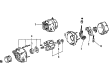
2005 Toyota Echo Alternator
Part Number: 27060-21031-84$144.24 MSRP: $189.72You Save: $45.48 (24%)Ships in 1-3 Business DaysProduct Specifications- Other Name: Alternator Assembly, With Regulator
- Item Weight: 14.80 Pounds
- Item Dimensions: 13.2 x 10.9 x 9.0 inches
- Condition: New
- SKU: 27060-21031-84
- Warranty: This genuine part is guaranteed by Toyota's factory warranty.
2005 Toyota Echo Alternator
Part Number: 27060-21042$441.50 MSRP: $647.03You Save: $205.53 (32%)Ships in 1-3 Business DaysProduct Specifications- Other Name: Alternator Assembly, With Regulator
- Replaces: 27060-21041
- Condition: New
- SKU: 27060-21042
- Warranty: This genuine part is guaranteed by Toyota's factory warranty.
2005 Toyota Echo Alternator
Looking for affordable OEM 2005 Toyota Echo Alternator? Explore our comprehensive catalogue of genuine 2005 Toyota Echo Alternator. All our parts are covered by the manufacturer's warranty. Plus, our straightforward return policy and speedy delivery service ensure an unparalleled shopping experience. We look forward to your visit!
2005 Toyota Echo Alternator Parts Q&A
- Q: How to service and repair the alternator on 2005 Toyota Echo?A: Service and repair of the alternator begins with component separation starting with the removal of the rear end cover through terminal insulator and nut clearance followed by bolt and 3 nuts and end cover and plate terminal in sequence. First detach the brush holder and voltage regulator by removing the brush holder cover along with 5 screws and removing the brush holder and voltage regulator from the device. Afterward remove the seal plate from the rectifier end frame. The rectifier holder requires removal of its four screws followed by the holder itself then four rubber insulators. Begin by mounting Special Service Tool 09820-63011 into the torque wrench which enables a proper connection to the rotor shaft before turning the socket clockwise to 39 Nm (400 kgf.cm, 29 ft.lbf). Securely attach the tool while avoiding full nut rotation on the pulley when turning it counterclockwise to prevent rotor shaft damage. First remove the adapter generator from its holder before taking away the socket and pulley holding tool that leads to pulley removal and finally the pulley nut and pulley extraction. Remove the 4 nuts and wire clip and use Special Service Tool 09286-46011 to disconnect the rectifier end frame before taking off the generator washer from the rotor. The reassembly process starts with inserting the rotor directly onto the drive end frame while placing the rectifier end frame first on the pulley and then placing the rotor on top of the rectifier end frame. Mount the generator washer onto the rotor followed by using a 29 mm socket wrench to tighten the rectifier end frame while attaching it with wire clip and 4 nuts, where torque setting for Nut A is 4.5 N.m (46 kgf.cm, 40 in.lb) and Nut B needs 5.4 N.m (55 kgf.cm, 48 in.lb) torque. The nut will be tightened by hand first before torquing it to 39 N.m (398 kg.cm, 29 ft.lb) using the pulley holding tool (Special Service Tool 09820-63011) and finally to 111 N.m (1,132 kg.cm, 82 ft.lb). The installation of the rectifier holder occurs by inserting its 4 rubber insulators right while maintaining proper orientation and fastening the holder through 4 screws tightened to 2.9 N.m (30 kgf.cm, 26 in.lbf). Install the seal plate onto the rectifier end frame followed by the voltage regulator and brush holder carrying the correct installation direction before employing 5 screws torqued to 2.0 N.m (20 kgf.cm, 18 in.lbf) then cover the brush holder. Position the rear end cover with the end cover and plate terminal while securing it through the bolt and 3 nuts which should be torqued at 4.4 N.m (45 kgf.cm, 39 in.lbf) for the nuts and 3.9 N.m (39 kgf.cm, 35 in.lbf) for the bolt. Also tighten the terminal insulator with its nut torqued to 4.1 N.m (42 kgf.cm, 36 in.lbf). Check whether the rotor spins without any signs of resistance.
Related 2005 Toyota Echo Parts
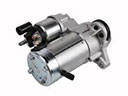 2005 Toyota Echo Starter Motor
 2005 Toyota Echo Starter Solenoid
 2005 Toyota Echo Alternator Brush
 2005 Toyota Echo Alternator Pulley
 2005 Toyota Echo Armature
 2005 Toyota Echo Battery Terminal
 2005 Toyota Echo Battery Tray
 2005 Toyota Echo Car Batteries
 2005 Toyota Echo Starter Brush
 2005 Toyota Echo Starter Drive Gear
 2005 Toyota Echo Voltage Regulator