×
ToyotaParts- Hello
- Login or Register
- Quick Links
- Live Chat
- Track Order
- Parts Availability
- RMA
- Help Center
- Contact Us
- Shop for
- Toyota Parts
- Scion Parts
My Garage
My Account
Cart
OEM 2005 Toyota Celica Starter Motor
Starter Ignition- Select Vehicle by Model
- Select Vehicle by VIN
Select Vehicle by Model
orMake
Model
Year
Select Vehicle by VIN
For the most accurate results, select vehicle by your VIN (Vehicle Identification Number).
4 Starter motors found

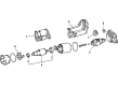
2005 Toyota Celica Starter
Part Number: 28100-22070-84$208.11 MSRP: $295.92You Save: $87.81 (30%)Ships in 1-3 Business DaysProduct Specifications- Other Name: Reman Starter; Starter Motor
- Replaces: 28100-22070
- Item Weight: 11.10 Pounds
- Item Dimensions: 16.1 x 8.6 x 8.4 inches
- Condition: New
- SKU: 28100-22070-84
- Warranty: This genuine part is guaranteed by Toyota's factory warranty.
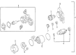
2005 Toyota Celica Starter
Part Number: 28100-22050-84$208.11 MSRP: $295.92You Save: $87.81 (30%)Ships in 1-3 Business DaysProduct Specifications- Other Name: Reman Starter; Starter Motor
- Replaces: 28100-22050
- Item Weight: 11.90 Pounds
- Item Dimensions: 16.1 x 8.8 x 8.3 inches
- Condition: New
- SKU: 28100-22050-84
- Warranty: This genuine part is guaranteed by Toyota's factory warranty.
- Product Specifications
- Other Name: Reman Starter Assembly; Starter Motor
- Replaces: 28100-22080
- Item Weight: 9.20 Pounds
- Item Dimensions: 10.5 x 7.4 x 5.3 inches
- Condition: New
- SKU: 28100-22080-84
- Warranty: This genuine part is guaranteed by Toyota's factory warranty.

 Product Specifications
- Other Name: Reman Starter Assembly; Starter Motor
- Replaces: 28100-22060
- Item Weight: 9.30 Pounds
- Item Dimensions: 10.3 x 7.1 x 5.1 inches
- Condition: New
- SKU: 28100-22060-84
- Warranty: This genuine part is guaranteed by Toyota's factory warranty.
2005 Toyota Celica Starter Motor
Looking for affordable OEM 2005 Toyota Celica Starter Motor? Explore our comprehensive catalogue of genuine 2005 Toyota Celica Starter Motor. All our parts are covered by the manufacturer's warranty. Plus, our straightforward return policy and speedy delivery service ensure an unparalleled shopping experience. We look forward to your visit!
2005 Toyota Celica Starter Motor Parts Q&A
- Q: How to service and repair the starter motor on 2005 Toyota Celica?A: Service and repair of the starter motor begins by removing the upper radiator support seal while also taking out the air cleaner assembly combined with both engine under covers of the right hand side and left hand side. Unplug the starter connector before removing the nut which unclips the starter wire then remove the two bolts holding the starter in place. Install the starter by positioning it correctly on the mounting points and fasten with two bolts which need to be 64 mm (2.72 in.) for A and 54 mm (2.13 in.) for B. Then connect the starter wire and install the nut before connecting the starter connector. Proceed by reattaching the RH and LH engine under covers as well as the air cleaner assembly and upper radiator support seal.
Related 2005 Toyota Celica Parts
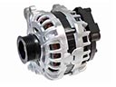 2005 Toyota Celica Alternator
 2005 Toyota Celica Starter Solenoid
 2005 Toyota Celica Alternator Bracket
 2005 Toyota Celica Alternator Pulley
 2005 Toyota Celica Armature
 2005 Toyota Celica Battery Cable
 2005 Toyota Celica Battery Terminal
 2005 Toyota Celica Battery Tray
 2005 Toyota Celica Car Batteries
 2005 Toyota Celica Starter Brush
 2005 Toyota Celica Starter Drive Gear
 2005 Toyota Celica Voltage Regulator