×
ToyotaParts- Hello
- Login or Register
- Quick Links
- Live Chat
- Track Order
- Parts Availability
- RMA
- Help Center
- Contact Us
- Shop for
- Toyota Parts
- Scion Parts
My Garage
My Account
Cart
OEM 2004 Toyota Solara Air Bag Sensor
Air Bag Impact Sensor- Select Vehicle by Model
- Select Vehicle by VIN
Select Vehicle by Model
orMake
Model
Year
Select Vehicle by VIN
For the most accurate results, select vehicle by your VIN (Vehicle Identification Number).
9 Air Bag Sensors found

2004 Toyota Solara Side Impact Sensor, Driver Side
Part Number: 89830-06020$227.08 MSRP: $278.48You Save: $51.40 (19%)Ships in 1-3 Business DaysProduct Specifications- Other Name: Sensor Assembly, Side Air Bag; Air Bag Impact Sensor, Left; Air Bag Sensor; Side Sensor; Sensor Assembly, Side Air Bag, Driver Side
- Position: Driver Side
- Part Name Code: 89860A
- Item Weight: 0.60 Pounds
- Item Dimensions: 4.3 x 2.7 x 2.1 inches
- Condition: New
- Fitment Type: Direct Replacement
- SKU: 89830-06020
- Warranty: This genuine part is guaranteed by Toyota's factory warranty.
2004 Toyota Solara Side Impact Sensor, Passenger Side
Part Number: 89860-06060$212.37 MSRP: $260.44You Save: $48.07 (19%)Ships in 1-3 Business DaysProduct Specifications- Other Name: Sensor Assembly, Side Air Bag; Air Bag Impact Sensor, Right; Air Bag Sensor; Side Sensor; Sensor Assembly, Side Air Bag, Passenger Side
- Position: Passenger Side
- Part Name Code: 89860
- Item Weight: 0.60 Pounds
- Item Dimensions: 4.3 x 2.7 x 2.0 inches
- Condition: New
- Fitment Type: Direct Replacement
- SKU: 89860-06060
- Warranty: This genuine part is guaranteed by Toyota's factory warranty.
2004 Toyota Solara Side Impact Sensor, Passenger Side
Part Number: 89860-06040$191.37 MSRP: $234.70You Save: $43.33 (19%)Ships in 1-3 Business DaysProduct Specifications- Other Name: Sensor Assembly, Side Air Bag; Air Bag Impact Sensor, Right; Air Bag Sensor; Side Sensor; Sensor Assembly, Side Air Bag, Passenger Side
- Position: Passenger Side
- Part Name Code: 89860
- Item Weight: 0.60 Pounds
- Item Dimensions: 4.3 x 2.5 x 2.0 inches
- Condition: New
- Fitment Type: Direct Replacement
- SKU: 89860-06040
- Warranty: This genuine part is guaranteed by Toyota's factory warranty.

2004 Toyota Solara Side Impact Sensor, Rear Driver Side
Part Number: 89834-06020$120.97 MSRP: $171.24You Save: $50.27 (30%)Ships in 1-3 Business DaysProduct Specifications- Other Name: Sensor, Air Bag, Rear; Air Bag Impact Sensor, Left; Air Bag Sensor; Side Sensor; Sensor, Air Bag, Rear Driver Side
- Manufacturer Note: SRS AIR BAG-W/CURTAIN
- Position: Rear Driver Side
- Part Name Code: 89834
- Item Weight: 0.60 Pounds
- Item Dimensions: 4.4 x 2.6 x 2.1 inches
- Condition: New
- Fitment Type: Direct Replacement
- SKU: 89834-06020
- Warranty: This genuine part is guaranteed by Toyota's factory warranty.
2004 Toyota Solara Side Impact Sensor, Rear Passenger Side
Part Number: 89833-06020$124.26 MSRP: $175.90You Save: $51.64 (30%)Ships in 1-3 Business DaysProduct Specifications- Other Name: Sensor, Air Bag, Rear; Air Bag Impact Sensor, Right; Air Bag Sensor; Side Sensor; Sensor, Air Bag, Rear Passenger Side
- Manufacturer Note: SRS AIR BAG-W/CURTAIN
- Position: Rear Passenger Side
- Part Name Code: 89833
- Item Weight: 0.60 Pounds
- Item Dimensions: 4.3 x 2.5 x 2.0 inches
- Condition: New
- Fitment Type: Direct Replacement
- SKU: 89833-06020
- Warranty: This genuine part is guaranteed by Toyota's factory warranty.

2004 Toyota Solara Position Sensor, Driver Side
Part Number: 89178-33031$101.66 MSRP: $142.69You Save: $41.03 (29%)Ships in 1-3 Business DaysProduct Specifications- Other Name: Sensor, Seat Position; Air Bag Seat Sensor Mat, Front Left; Seat Track Position Sensor, Left; Air Bag Sensor; Occupant Sensor; Discriminating Sensor; Sensor, Seat Position Air Bag
- Position: Driver Side
- Replaces: 89178-33030
- Part Name Code: 89178A
- Item Weight: 0.50 Pounds
- Item Dimensions: 2.1 x 1.6 x 1.3 inches
- Condition: New
- Fitment Type: Direct Replacement
- SKU: 89178-33031
- Warranty: This genuine part is guaranteed by Toyota's factory warranty.

2004 Toyota Solara Position Sensor, Front Driver Side
Part Number: 89178-33020$99.17 MSRP: $139.20You Save: $40.03 (29%)Ships in 1-3 Business DaysProduct Specifications- Other Name: Sensor, Seat Position; Seat Track Position Sensor, Front Left; Air Bag Seat Sensor Mat, Front Left; Air Bag Sensor; Occupant Sensor; Discriminating Sensor; Sensor, Seat Position Air Bag
- Position: Front Driver Side
- Part Name Code: 89178A
- Item Weight: 0.50 Pounds
- Item Dimensions: 2.2 x 1.6 x 1.3 inches
- Condition: New
- Fitment Type: Direct Replacement
- SKU: 89178-33020
- Warranty: This genuine part is guaranteed by Toyota's factory warranty.
- Product Specifications
- Other Name: Sensor Assembly, Side Air Bag; Air Bag Impact Sensor, Left; Air Bag Sensor; Side Sensor; Sensor Assembly, Side Air Bag, Driver Side
- Position: Driver Side
- Part Name Code: 89860A
- Item Weight: 0.60 Pounds
- Item Dimensions: 4.3 x 2.6 x 2.0 inches
- Condition: New
- Fitment Type: Direct Replacement
- SKU: 89830-06030
- Warranty: This genuine part is guaranteed by Toyota's factory warranty.
 Product Specifications
- Other Name: Sensor, Air Bag, Front; Air Bag Impact Sensor; Air Bag Sensor; Front Sensor; Sensor, Air Bag, Front Passenger Side; Sensor, Air Bag, Front Driver Side
- Position: Front
- Item Weight: 0.70 Pounds
- Item Dimensions: 4.8 x 2.9 x 2.3 inches
- Condition: New
- Fitment Type: Direct Replacement
- SKU: 89173-09220
- Warranty: This genuine part is guaranteed by Toyota's factory warranty.
2004 Toyota Solara Air Bag Sensor
Looking for affordable OEM 2004 Toyota Solara Air Bag Sensor? Explore our comprehensive catalogue of genuine 2004 Toyota Solara Air Bag Sensor. All our parts are covered by the manufacturer's warranty. Plus, our straightforward return policy and speedy delivery service ensure an unparalleled shopping experience. We look forward to your visit!
2004 Toyota Solara Air Bag Sensor Parts Q&A
- Q: How to service and repair the Impact Sensor and Side Air Bag Sensor on 2004 Toyota Solara?A: Service and repair procedures for the Impact Sensor and Side Air Bag Sensor should start with disconnecting the connector by gripping both outer flank sides and following the arrow direction to release its lock mechanism. Both outer flank sides should be held while disconnecting the connector since connecting from the top or bottom makes the operation more challenging. Alignment of the connector should follow the illustrated position until the outer reaches its initial formation while the locking produces a audible click. You should not hold the outer element when performing connections to protect from bad connections.
Related 2004 Toyota Solara Parts
 2004 Toyota Solara ABS Relay
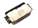 2004 Toyota Solara Air Bag
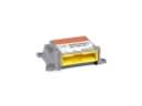 2004 Toyota Solara Air Bag Control Module
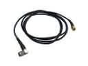 2004 Toyota Solara Antenna Cable
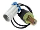 2004 Toyota Solara Back Up Light Switch
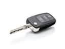 2004 Toyota Solara Car Key
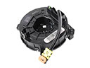 2004 Toyota Solara Clock Spring
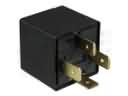 2004 Toyota Solara Daytime Running Light Relay
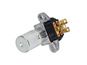 2004 Toyota Solara Dimmer Switch
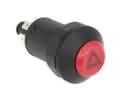 2004 Toyota Solara Hazard Warning Switch
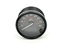 2004 Toyota Solara Speedometer
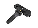 2004 Toyota Solara TPMS Sensor