×
ToyotaParts- Hello
- Login or Register
- Quick Links
- Live Chat
- Track Order
- Parts Availability
- RMA
- Help Center
- Contact Us
- Shop for
- Toyota Parts
- Scion Parts
My Garage
My Account
Cart
OEM 2004 Toyota Highlander Fuel Tank
Gas Tank- Select Vehicle by Model
- Select Vehicle by VIN
Select Vehicle by Model
orMake
Model
Year
Select Vehicle by VIN
For the most accurate results, select vehicle by your VIN (Vehicle Identification Number).
1 Fuel Tank found

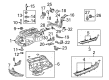
2004 Toyota Highlander Tank Sub-Assembly, Fuel
Part Number: 77001-0E010$1012.18 MSRP: $1483.37You Save: $471.19 (32%)Ships in 1-3 Business DaysProduct Specifications- Other Name: TANK SUB-ASSY, FUEL; Fuel Tank
- Item Weight: 27.90 Pounds
- Item Dimensions: 38.9 x 31.6 x 12.2 inches
- Condition: New
- SKU: 77001-0E010
- Warranty: This genuine part is guaranteed by Toyota's factory warranty.
2004 Toyota Highlander Fuel Tank
Achieve unprecedented performance experience with our genuine 2004 Toyota Highlander Fuel Tank. All our parts are engineered for a perfect fit and maximum durability to ensure that your Highlander returns to factory condition. Specially designed for the 2004 Toyota Highlander, this Fuel Tank offers superior reliability and ease of installation for anyone.
Looking for affordable OEM 2004 Toyota Highlander Fuel Tank? Explore our comprehensive catalogue of genuine 2004 Toyota Highlander Fuel Tank. All our parts are covered by the manufacturer's warranty. Plus, our straightforward return policy and speedy delivery service ensure an unparalleled shopping experience. We look forward to your visit!
Related 2004 Toyota Highlander Parts
 2004 Toyota Highlander Fuel Filter
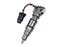 2004 Toyota Highlander Fuel Injector
 2004 Toyota Highlander Fuel Pump
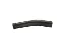 2004 Toyota Highlander Fuel Filler Hose
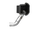 2004 Toyota Highlander Fuel Filler Neck
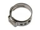 2004 Toyota Highlander Fuel Line Clamps
 2004 Toyota Highlander Fuel Pressure Regulator
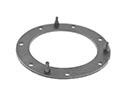 2004 Toyota Highlander Fuel Pump Gasket
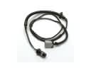 2004 Toyota Highlander Fuel Pump Wiring Harness
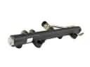 2004 Toyota Highlander Fuel Rail
 2004 Toyota Highlander Fuel Tank Lock Ring
 2004 Toyota Highlander Intake Manifold Gasket