×
ToyotaParts- Hello
- Login or Register
- Quick Links
- Live Chat
- Track Order
- Parts Availability
- RMA
- Help Center
- Contact Us
- Shop for
- Toyota Parts
- Scion Parts
My Garage
My Account
Cart
OEM 2004 Toyota Avalon Fuel Injector
Gas Injector- Select Vehicle by Model
- Select Vehicle by VIN
Select Vehicle by Model
orMake
Model
Year
Select Vehicle by VIN
For the most accurate results, select vehicle by your VIN (Vehicle Identification Number).
1 Fuel Injector found

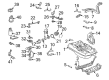
2004 Toyota Avalon Injector Assembly, Fuel
Part Number: 23209-0A010$193.38 MSRP: $276.10You Save: $82.72 (30%)Ships in 1-3 Business DaysProduct Specifications- Other Name: Injector Set, Fuel; Fuel Injector
- Replaces: 23209-20020
- Part Name Code: 23250
- Item Weight: 0.50 Pounds
- Item Dimensions: 3.8 x 2.8 x 1.5 inches
- Condition: New
- Fitment Type: Direct Replacement
- Require Quantity: 6
- SKU: 23209-0A010
- Warranty: This genuine part is guaranteed by Toyota's factory warranty.
2004 Toyota Avalon Fuel Injector
Looking for affordable OEM 2004 Toyota Avalon Fuel Injector? Explore our comprehensive catalogue of genuine 2004 Toyota Avalon Fuel Injector. All our parts are covered by the manufacturer's warranty. Plus, our straightforward return policy and speedy delivery service ensure an unparalleled shopping experience. We look forward to your visit!
2004 Toyota Avalon Fuel Injector Parts Q&A
- Q: What precautions should be observed when servicing fuel injectors on 2004 Toyota Avalon?A: Follow the safety guidelines when servicing fuel injectors which include avoiding reusing the O-ring while you must be gentle while installing new O-rings and apply spindle oil or gasoline to coat them before installation but exclude engine, gear or brake oil from the procedure. Start by removing the V-bank cover through the use of a 5 mm hexagon wrench along with counterclockwise loosening of fasteners while removing the 3 cap nuts. Proceed with removing the air cleaner hose with resonator then the air intake chamber assembly before disconnecting the injector connectors. Loosen the clamp securing the fuel hose before disconnecting the fuel tube connector from the outlet of the fuel filter while remembering to take safety precautions because the fuel line contains residual pressure. The service process requires removal of delivery pipes and injectors through five bolt removal with delivery pipes and six injectors and No.1 fuel pipe before extracting the four spacers from the intake manifold to pull out six injectors and discarding all eight O-rings and grommets from each injector unit. The installation process starts with mounting new grommets and insulators onto each injector while the application of a small oil or gasoline layer onto 2 new O-rings before installing them. Place a small amount of spindle oil or gasoline on the delivery pipe contact point with the injector O-ring before rotating the injector to fit it into the delivery pipe and place all 6 injectors while their connectors need to face outward. The first step involves placing four spacers onto the intake manifold before treating all contact areas between the intake manifold and injector O-ring with a spindle oil or gasoline coating. The delivery pipes and fuel pipe with installable 6 injectors should be positioned onto the intake manifold. The delivery pipe bolts and No.1 fuel pipe bolt need temporary installation to check injector rotation; if the injectors are not smooth, replace the O-rings. Secure the delivery pipes with 4 bolts at 10 N.m (100 kgf.cm and 7 ft.lbf) and fasten the No. 1 fuel pipe bolt to 19.5 N.m (200 kgf.cm and 14 ft.lbf). Attach the No.1 fuel pipe by matching white paint markings while securing the fuel tube connector to the fuel filter followed by fuel hose clamp installation that produces a distinct "click" sound and verifying clamp fixation. The installation includes fitting the air assist hoses and pipe followed by attaching the injector connectors before proceeding with the air intake chamber assembly and air cleaner hose with resonator installation and finally securing the V-bank cover through cap nut usage with a 5 mm hexagon wrench and by pressing down the fastener. Lastly, check for fuel leaks.
Related 2004 Toyota Avalon Parts
 2004 Toyota Avalon Fuel Filter
 2004 Toyota Avalon Fuel Pump
 2004 Toyota Avalon Fuel Tank
 2004 Toyota Avalon Fuel Filler Hose
 2004 Toyota Avalon Fuel Filler Neck
 2004 Toyota Avalon Fuel Level Sensor
 2004 Toyota Avalon Fuel Line Clamps
 2004 Toyota Avalon Fuel Pressure Regulator
 2004 Toyota Avalon Fuel Pump Gasket
 2004 Toyota Avalon Fuel Pump Seal
 2004 Toyota Avalon Fuel Tank Strap
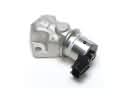 2004 Toyota Avalon Idle Control Valve