×
ToyotaParts- Hello
- Login or Register
- Quick Links
- Live Chat
- Track Order
- Parts Availability
- RMA
- Help Center
- Contact Us
- Shop for
- Toyota Parts
- Scion Parts
My Garage
My Account
Cart
OEM 2003 Toyota Sienna Timing Belt
Engine Timing Belt- Select Vehicle by Model
- Select Vehicle by VIN
Select Vehicle by Model
orMake
Model
Year
Select Vehicle by VIN
For the most accurate results, select vehicle by your VIN (Vehicle Identification Number).
1 Timing Belt found


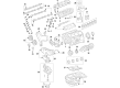
2003 Toyota Sienna Timing Belt
Part Number: 13568-09080$60.54 MSRP: $84.98You Save: $24.44 (29%)Ships in 1-2 Business DaysProduct Specifications- Other Name: Belt, Timing; Engine Timing Belt; Timing Belt Kit
- Replaces: 13568-09050
- Part Name Code: 13568
- Item Weight: 1.00 Pounds
- Item Dimensions: 14.0 x 12.1 x 2.1 inches
- Condition: New
- Fitment Type: Direct Replacement
- SKU: 13568-09080
- Warranty: This genuine part is guaranteed by Toyota's factory warranty.
2003 Toyota Sienna Timing Belt
Looking for affordable OEM 2003 Toyota Sienna Timing Belt? Explore our comprehensive catalogue of genuine 2003 Toyota Sienna Timing Belt. All our parts are covered by the manufacturer's warranty. Plus, our straightforward return policy and speedy delivery service ensure an unparalleled shopping experience. We look forward to your visit!
2003 Toyota Sienna Timing Belt Parts Q&A
- Q: How to remove and install the timing belt on 2003 Toyota Sienna?A: The first step to remove the timing belt requires disassembly of the outer front cowl top panel assembly together with removal of the right-hand front wheel while also taking out the right-hand fender apron seal. To begin the process remove the generator drive belt then the power steering pump drive belt by unwinding the two attachment bolts. Unclip three main components such as the water outlet as well as the ground strap connectors and DLC1 from the No. 2 right-hand engine mounting bracket. Start by detaching the right-hand engine mounting stay then remove the engine moving control rod after which take off the No. 2 right-hand engine mounting bracket. Finish the sequence by loosening the generator pivot bolt to disconnect the No. 2 generator bracket together with its nut and bracket. Make use of SST 09213-54015 (91651-60855) together with SST 09330-00021, 09950-50013 (09951-05010, 09952-05010, 09953-05010, 09953-05020, 09954-05021) to remove crankshaft pulley bolts before extracting the pulley. First disconnect the four bolts of the No. 1 timing belt cover before moving to the timing belt guide then proceed to remove the No. 2 timing belt cover by disconnecting engine wire protector clamps and removing five bolts. To remove the right-hand engine mounting bracket, first detach the two bolts, nut, and then the mounting bracket. To align the No. 1 cylinder at TDC/compression position use a crankshaft pulley bolt as an installation for a short period. This allows rotation of the crankshaft to align the pulley timing marks and the oil pump body and inspect the camshaft timing pulleys matching the No. 3 timing belt cover. A new installation marking system should be created to align with the timing marks on the timing pulleys when no marks exist on a reused timing belt. The timing belt tensioner should be removed by alternately adjusting the two bolts followed by removing the timing belt. You must remove the right-hand camshaft timing pulleys by using SST 09249-63010, 09960-10010 (09962-01000, 09963-01000) and the left-hand pulleys require SST 09960-10010 (09962-01000, 09963-01000). The repair continues with the removal of the No. 2 idler pulley and the No. 1 idler pulley through the use of a 10 mm hexagon wrench. Use SST 09950-50013 (09951-05010, 09952-05010, 09953-05010, 09953-05020, 09954-05011) to remove the crankshaft timing pulley despite ensuring the sensor remains unharmed after unbolted the timing belt plate and crankshaft bolt. Check the timing belt for any damages that would include bending, twisting or contact with moisture like oil or water or steam. Verify no signs of wear exist. The mechanism comprises checking idler pulleys for oil leakage while performing observations on the timing belt tensioner's push rod movement and its oil leakage status. Fit the crankshaft timing pulley by using the pulley set key as a guide for the key groove then push it on before attaching the timing belt plate using 8.0 Nm (80 kgf-cm, 69 inch lbs.) torque. The installation process of No. 1 idler pulley starts with applying adhesive part No. 08833-00080 followed by Three Bond 1344 or Loctite 242 or equivalent adhesive to the pulley before tightening it to 34 Nm (350 kgf-cm, 25 ft. lbs.). Finally, torque the No. 2 idler pulley to 43 Nm (440 kgf-cm, 32 ft. lbs.). Position the right-hand camshaft timing pulley with its flange side frontward while placing the knock pin in the proper groove before tightening the pulley bolt to 88 Nm using SST 09249-63010, 09960-10010 (09962-01000, 09963-01000). Install the left-hand camshaft timing pulley facing inward while tightening its bolt to 125 Nm (1,300 kgf-cm, 94 ft. lbs.) using SST 09960-10010 (09962-01000, 09963-01000). The No. 1 cylinder must be set to TDC/compression position with timing marks ready to align before installing the timing belt having its front mark facing forward while both installation marks should match the timing marks of the crankshaft and camshaft timing pulleys in their setup sequence. First set the timing belt tensioner by pushing the rod inside then fastening it with a 1.27 mm hexagon wrench before installing the tensioner bolts to 27 Nm (280 kgf-cm, 20 ft. lbs.). To verify valve timing position turn the crankshaft two rotations while ensuring all timing marks match; if the marks do not align repeat the timing belt installation process. Raise the torque on the right-hand engine mounting bracket to 28 Nm after (290 kgf-cm, 21 ft. lbs.) before integrating the No. 2 timing belt cover which must have an undamaged gasket and then torquing it to 8.5 Nm (85 kgf-cm, 74 inch lbs.). Position the timing belt guide towards the outside as you install the No. 1 timing belt cover along with a gasket that needs 8.5 Nm (85 kgf-cm, 74 inch lbs.) torque. Similarly install the crankshaft pulley with SST 09213-54015 (91651-60855), 09330-00021 to torque the pulley bolt to 215 Nm (2,200 kgf-cm, 159 ft. lbs.). The repair process begins with attaching the No. 2 generator bracket without bolt tightening then proceeds to the right-hand engine mounting bracket, engine moving control rod, and right-hand engine mounting stay installation. Before tightening the fasteners, position the DLC1 at the No. 2 right-hand engine mounting bracket as well as the ground strap connectors and engine coolant reservoir hose to the water outlet. The power steering pump drive belt and generator drive belt and right-hand fender apron seal and right-hand front wheel must be installed with the outer front cowl top panel assembly before conducting a vehicle road test to verify normal operating sounds and shocks and slippage and shift points and smooth performance.
Related 2003 Toyota Sienna Parts
 2003 Toyota Sienna Oil Filter
 2003 Toyota Sienna Camshaft
 2003 Toyota Sienna Crankshaft Gear
 2003 Toyota Sienna Cylinder Head Gasket
 2003 Toyota Sienna Dipstick
 2003 Toyota Sienna Dipstick Tube
 2003 Toyota Sienna Engine Mount Torque Strut
 2003 Toyota Sienna Exhaust Valve
 2003 Toyota Sienna Oil Pump
 2003 Toyota Sienna Oil Pump Gasket
 2003 Toyota Sienna Piston Ring Set
 2003 Toyota Sienna Rod Bearing