×
ToyotaParts- Hello
- Login or Register
- Quick Links
- Live Chat
- Track Order
- Parts Availability
- RMA
- Help Center
- Contact Us
- Shop for
- Toyota Parts
- Scion Parts
My Garage
My Account
Cart
OEM 2003 Toyota RAV4 Timing Chain Tensioner
Engine Timing Chain Tensioner- Select Vehicle by Model
- Select Vehicle by VIN
Select Vehicle by Model
orMake
Model
Year
Select Vehicle by VIN
For the most accurate results, select vehicle by your VIN (Vehicle Identification Number).
1 Timing Chain Tensioner found


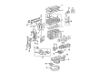
2003 Toyota RAV4 Tensioner Assembly, Chain
Part Number: 13540-0H010$97.51 MSRP: $136.87You Save: $39.36 (29%)Ships in 1 Business DayProduct Specifications- Other Name: Timing Chain Tensioner; Belt Tensioner
- Replaces: 13540-0H030, 13540-28010
- Part Name Code: 13540
- Item Weight: 1.00 Pounds
- Item Dimensions: 5.7 x 3.4 x 2.7 inches
- Condition: New
- Fitment Type: Direct Replacement
- SKU: 13540-0H010
- Warranty: This genuine part is guaranteed by Toyota's factory warranty.
2003 Toyota RAV4 Timing Chain Tensioner
Looking for affordable OEM 2003 Toyota RAV4 Timing Chain Tensioner? Explore our comprehensive catalogue of genuine 2003 Toyota RAV4 Timing Chain Tensioner. All our parts are covered by the manufacturer's warranty. Plus, our straightforward return policy and speedy delivery service ensure an unparalleled shopping experience. We look forward to your visit!
2003 Toyota RAV4 Timing Chain Tensioner Parts Q&A
- Q: How to service and repair the Timing Chain Tensioner on 2003 Toyota RAV4?A: In order to fix the Timing Chain Tensioner, one needs to empty the engine oil and remove a number of components such as cylinder head cover. Install the TDC on Set No. 1 cylinder and remove the chain tensioner and check the timing chain and sprockets. Refill engine oil by replacing damaged parts, reattaching components and checking leaks.
Related 2003 Toyota RAV4 Parts
 2003 Toyota RAV4 Engine Mount
 2003 Toyota RAV4 Oil Pump
 2003 Toyota RAV4 Valve Cover Gasket
 2003 Toyota RAV4 Cam Gear
 2003 Toyota RAV4 Camshaft
 2003 Toyota RAV4 Camshaft Bearing
 2003 Toyota RAV4 Crankshaft Gear
 2003 Toyota RAV4 Drain Plug Washer
 2003 Toyota RAV4 Intake Valve
 2003 Toyota RAV4 Oil Pump Gasket
 2003 Toyota RAV4 Piston
 2003 Toyota RAV4 Valve Stem Seal