×
ToyotaParts- Hello
- Login or Register
- Quick Links
- Live Chat
- Track Order
- Parts Availability
- RMA
- Help Center
- Contact Us
- Shop for
- Toyota Parts
- Scion Parts
My Garage
My Account
Cart
OEM 2002 Toyota 4Runner Timing Belt
Engine Timing Belt- Select Vehicle by Model
- Select Vehicle by VIN
Select Vehicle by Model
orMake
Model
Year
Select Vehicle by VIN
For the most accurate results, select vehicle by your VIN (Vehicle Identification Number).
1 Timing Belt found


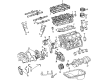
2002 Toyota 4Runner Timing Belt
Part Number: 13568-YZZ03$58.42 MSRP: $81.32You Save: $22.90 (29%)Ships in 1-3 Business DaysProduct Specifications- Other Name: Belt Set, Timing; Engine Timing Belt; Timing Belt Kit
- Replaces: 13568-69095
- Item Weight: 1.00 Pounds
- Condition: New
- SKU: 13568-YZZ03
- Warranty: This genuine part is guaranteed by Toyota's factory warranty.
2002 Toyota 4Runner Timing Belt
Looking for affordable OEM 2002 Toyota 4Runner Timing Belt? Explore our comprehensive catalogue of genuine 2002 Toyota 4Runner Timing Belt. All our parts are covered by the manufacturer's warranty. Plus, our straightforward return policy and speedy delivery service ensure an unparalleled shopping experience. We look forward to your visit!
2002 Toyota 4Runner Timing Belt Parts Q&A
- Q: How to Properly Remove and Install a Timing Belt on 2002 Toyota 4Runner?A: Engine coolant draining and upper radiator hose disconnection along with the engine under cover removal are required at the beginning of timing belt removal process. The procedure starts by detaching the PS pump from the engine through the removal of PS air hoses at the air intake chamber and resonator followed by the unfastening of the frame PS pressure tube clamp bolt and the separation of the drive belt and its two mounting hardware pieces to cut off the PS pump. Disconnect the A/C compressor from the engine by taking out the connector, drive belt and four bolts when A/C features are present. The maintenance of engine starts with unlatching the fan through its fluid coupling and fan pulleys while discarding the generator drive belt before extracting the No.2 fan shroud along with fan pulleys and fluid coupling. The A/C compressor bracket needs to be removed from A/C equipped models by disconnecting its five bolts. Use bolt removal procedures to take out the dipstick along with guide and O-ring while removing the bolt. You must disconnect the No.2 timing belt cover by removing the high-tension cord clamps followed by six bolts and the camshaft position sensor connector disconnection. Begin by detaching the fan bracket through absorption of the nut and PS pump adjusting strut, after which you should remove the bolt, nut and fan bracket. Loosen the crankshaft pulley bolt with SST 09213-54015 (90119-08216) and 09330-00021 and then remove SST, the pulley bolt and pulley with SST 09950-50013 (09951-05010, 09952-05010, 09953-05020, 09954-05031). Legitimately detach the starter wire bracket and the No.1 timing belt cover after removing two bolts from the bracket and four bolts from the cover. Set Number one cylinder at Top Dead Center/Compression by first installing the crankshaft pulley bolt until the crankshaft times correctly then check for camshaft timing pulley alignment with the Number three timing belt cover. A new check mark installation is required before removing the timing belt unless three existing installation marks and a front mark remain visible. First loosen two bolts attached to the timing belt tensioner alternately before removing it and then proceed to remove the timing belt. Starting with SST 09960-10010 (also works with 09962-01000 and 09963-01000) to unscrew the camshaft timing pulley bolt, finish by removing bolt and knock pin and camshaft timing pulley from the RH side. The procedure must also be done on the LH camshaft timing pulley. Start with the removal of No.2 idler pulley bolt before proceeding to extract the pivot bolt from No.1 idler pulley along with its pulley and plate washer. To remove the crankshaft timing pulley you must use SST with a service bolt when needed. The timing belt requires inspection to ensure it has no bends, twists or contact with oil or water or steam and displays proper installation without wear. Verify that idler pulleys show no oil leakage and function without disturbance and examine timing belt tensioner for oil leaks while checking its push rod executes proper movement. The push rod measurement needs replacement of the tensioner if it falls outside the 10.0 to 10.8 mm (0.394 to 0.425 inch) range. During installation first place the crankshaft timing pulley into its key groove before sliding on the part then install the No.1 idler pulley using 35 Nm torque (350 kgf-cm, 26 ft. lbs.) before performing a smooth movement check. The installation of the No.2 idler pulley requires 40 Nm torque while inspecting its smooth operational behavior. To install the LH camshaft timing pulley you must position the flange side in the outward direction while aligning the knock pin. Then use SST to install the pulley bolt with a torque of 110 Nm (1,100 kgf-cm, 81 ft. lbs.). Reposition the RH camshaft timing pulley according to those same installation steps. Place the No.1 cylinder at TDC/compression while installing the timing belt which should be clean and positioned correctly at the timing marks. After pressing the push rod of the timing belt tensioner apply a hexagon wrench to secure it and install the tensioner while tightening its bolts to 27 Nm (280 kgf-cm, 20 ft. lbs.). Adjust the valve timing alignment while ensuring proper placement of the timing marks before fitting both the No.1 timing belt cover and starter wire bracket along with their correct torques. The crankshaft pulley receives installation and a proper alignment process alongside torque requirements of 300 Nm (3,000 kgf-cm, 217 ft. lbs.). Secure the fan bracket together with the No.2 timing belt cover along with the oil dipstick and guide and A/C compressor bracket (if installed) by applying correct torques on every component. First mount the components with fan coupling and pulleys and install the No.2 fan shroud. Then adjust the generator drive belt followed by fan assembly tightening. First attach the A/C compressor to the engine while securing all elements with torques at their designated values. The same process should be used to connect the PS pump. The procedure ends with reconnecting the upper radiator hose followed by filling the engine with coolant then engine start to verify leaks and reinstalling the engine under cover prior to executing a road test and inspecting engine coolant status.
Related 2002 Toyota 4Runner Parts
 2002 Toyota 4Runner Oil Filter
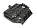 2002 Toyota 4Runner Engine Cover
 2002 Toyota 4Runner Oil Pump
 2002 Toyota 4Runner Cam Gear
 2002 Toyota 4Runner Camshaft
 2002 Toyota 4Runner Cylinder Head Gasket
 2002 Toyota 4Runner Dipstick
 2002 Toyota 4Runner Exhaust Valve
 2002 Toyota 4Runner Piston
 2002 Toyota 4Runner Timing Chain Tensioner
 2002 Toyota 4Runner Timing Cover
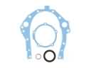 2002 Toyota 4Runner Timing Cover Gasket