My Garage
Cart
Make sure this part fits

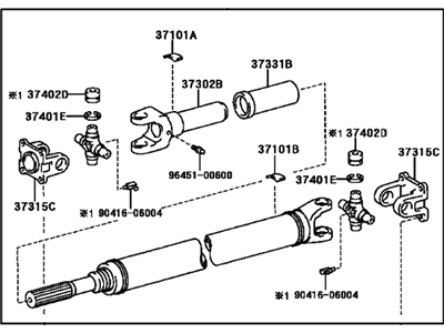
Toyota 37110-6A650
Shaft Assembly, Propeller

2003-2007 Toyota Land Cruiser 371106A650

Customer Questions & Expert Answers (5)
Toyota 37110-6A650 Shaft Assembly, Propeller
  • Part Description
    Driveshaft
  • Part Name Code
    37110
  • Manufacturer
    Toyota
Make sure this part fits
$460.69 MSRP: $675.14
You Save: $214.45 (32%)
Ships in 1-3 Business Days
1
ADD TO CART
  • Related Parts
  • Product Specifications
  • Vehicle Fitment
  • Customer Questions & Expert Answers
  • Product Specifications

    BrandGenuine Toyota
    Part Name Code37110
    Manufacturer Part Number37110-6A650
    Part DescriptionDriveshaft
    Item Dimensions59.9 x 12.8 x 7.3 inches
    Item Weight42.40 Pounds
    ConditionNew
    Fitment TypeDirect Replacement
    ManufacturerToyota
    SKU37110-6A650
    WarrantyThis genuine Toyota part is guaranteed by Toyota's factory warranty.
    Shipping & ReturnShipping Policy Return Policy
    Warning: California's Proposition 65
  • Vehicle Fitment

    Year Make Model Trim Engine
    2003-2007 Toyota Land CruiserBase8 Cyl 4.7 L GAS
  • Customer Questions & Expert Answers

    Q:
    Can you provide the right 37110-6A650 for my car? Posted by ToyotaPartsNow Specialist
    A:
    Find out if part number 37110-6A650 is the right fit for your car by Selecting Your Vehicle model.
    Posted by ToyotaPartsNow Specialist
    Q:
    How to Service and Repair a Drive Shaft on Toyota Land Cruiser? Posted by Customer
    A:
    Begin the front drive shaft service and repair by using 131 Nm torque to remove the front wheel. The front disc brake cylinder assembly needs to be disconnected by removing the steering knuckle bolt and flexible hose (torque: 28 Nm (290 kgf-cm, 21 ft. lbs.)) followed by the two bolts and washers and brake cylinder (torque: 123 Nm (1,250 kgf-cm, 91 ft. lbs.)) with proper support of the brake cylinder. The front drive shaft snap ring can be removed using a combination of a screwdriver and hammer on the grease cap followed by snap ring pliers for snap ring extraction. Required tools for this task include a torque wrench set to measure 71 inch lbs. (82 kgf-cm) and three bolts. Use a torque wrench to detach the ABS speed sensor and wire harness by removing those three bolts. You must disconnect the steering knuckle arm which requires removal of two bolts threaded to 147 Nm (1,500 kgf-cm, 108 ft. lbs.). After cleaning the bolt threads you must apply sealant specified as Part No. 08833-00070 or THREE BOND 1324 equivalent for installation. Steer clear of the cotter pin and nut at the steering knuckle (torque: 159 Nm (1,625 kgf-cm, 117 ft. lbs.)) while making necessary adjustments to the alignment using up to 60 degrees angle. Connect the lower suspension arm with the temporary nut as you secure the assembly with a jack using Special Service Tool 09628-62011. Disassemble the cotter pin and nut from the steering knuckle while applying 110 Nm (1,125 kgf-cm, 81 ft. lbs. torque). Additional tightening up to 60 degrees is required if the cotter pin holes are misaligned. The technician should utilize Special Service Tool: 09628-62011 to disconnect the steering knuckle from the upper suspension arm before extracting the nut and steering knuckle alongside the axle hub. The removal of the front drive shaft assembly requires using a brass bar and hammer for tapping out the drive shaft while ensuring protection of boot components alongside dust cover and oil seal before removing the snap ring from the inboard joint tulip with a screwdriver. You need to examine the outboard joint for its movement range then observe regular operation of the inboard joint combined with radial deformation and boot deterioration. The disassembly process starts with removing both inboard joint boot clamps by unstaking but keeping the inboard joint tulip and outboard joint shaft matchmarks from punching. After removing the outboard joint shaft snap ring the inboard joint tulip can be taken out. First remove the inboard joint boot clamps by unstaking them then mark the outboard joint shaft and both the inner race and cage with matchmarks. Finally remove the six balls from the joint and move the cage to the outboard joint side before using a snap ring expander to extract the snap ring then tap out the inner race with a brass bar accompanied by a hammer. Unstake the two outboard joint boot clamps but keep the outboard joint boot attached to it before removing the inboard and outboard joint boots without separating the outboard joint. Tap out the dust cover from the inboard joint tulip and the dust seal from the outboard joint shaft. Place a new dust seal onto the outboard joint shaft through use of Special Service Tool: 09950-00020 followed by installation of a new dust cover using Special Service Tool: 09316-20011. Implement the outboard joint boot while using two new clamps and apply vinyl tape on the spline to avoid damage before using Special Service Tool: 09521-24010 to pinch the inside clamp and apply grease to the outboard joint and boot according to the standard weight of 368 to 378 grams (13.0 to 13.3 ounces). Use Special Service Tool: 09240-00020 to adjust the outside clamp while positioning and pinching it until the clearance reaches 0.8 mm (0.031 inch). Construct the front axle inboard joint assembly by inserting the cage onto the outboard joint shaft with its compact inner section facing outward before matching the reference points while adding a new snap ring with snap ring expanding tool. Grease the six balls before loading them into the assembled cage of the inner race structure where matchmarks were previously aligned. The inboard joint tulip and boot required 293 to 303 grams (10.3 to 10.7 ounces) of grease packing before reinstallation of the outboard joint shaft. A new snap ring was installed. Mount the boot onto the inboard joint tulip while keeping it on the shaft groove and avoiding any deformation of the two boots during standard drive shaft length (A: 573.9 mm plus or minus 5.0 mm (22.594 inch plus or minus 0.197 inch)). Use clamps by bending them for lock and inspect the front drive shaft assembly both by reversing the removal sequence and testing the ABS speed sensor signal following installation.
    Posted by ToyotaPartsNow Specialist
    Q:
    What should be done to ensure proper axial play during reassembly for the 2006 Toyota Land Cruiser? Posted by Customer
    A:
    Install 2 new snap rings to allow 0 mm (0 inch) axial play and tap the yoke until there is no clearance between the bearing outer race and snap ring.
    Posted by ToyotaPartsNow Specialist
    See expert answers on similar Drive Shaft
    Q:
    How do you install the rear propeller shaft sliding shaft dust cover sub-assembly for the 2007 Toyota Land Cruiser? Posted by Customer
    A:
    Use Special Service Tool: 09636-20010 and a press, ensuring the universal joint is straight and applying MP grease to part 'A'.
    Posted by ToyotaPartsNow Specialist
    See expert answers on similar Drive Shaft
    Q:
    What should be done after installation for the 2004 Toyota Land Cruiser? Posted by Customer
    A:
    Pump MP grease into each fitting with a grease gun until grease flows around the oil seal.
    Posted by ToyotaPartsNow Specialist
    See expert answers on similar Drive Shaft
    If you have any questions about this product, please don't hesitate to ask us. We will be happy to help you!

OEM Toyota 37110-6A650, Excellent Performance and Perfect Fitment

To ensure reliability, purchase Toyota part # 37110-6A650 Shaft Assembly, Propeller. It is sometimes referred to as Toyota Drive Shaft. OEM parts are unrivaled in terms of quality. They go through extensive quality control inspections and are produced in accordance with Toyota's official factory specifications. All of these remove defects and imperfections. So you can relax knowing they promise exceptional lifespan and flawless fitment.

ToyotaPartsNow.com is a leading supplier of genuine Toyota parts such as Toyota 371106A650 Shaft Assembly, Propeller. At ToyotaPartsNow.com, we have a wide variety of OEM Toyota parts available at competitive prices. Our comprehensive range of genuine Toyota parts come with a manufacturer's warranty for peace of mind. We also prioritize customer satisfaction, providing a hassle-free return policy and expedited delivery for all our parts. For detailed Toyota parts information, click here.
Choose ToyotaPartsNow for discounted prices, exceptional service and fast delivery