×
ToyotaParts- Hello
- Login or Register
- Quick Links
- Live Chat
- Track Order
- Parts Availability
- RMA
- Help Center
- Contact Us
- Shop for
- Toyota Parts
- Scion Parts
My Garage
My Account
Cart
OEM 2005 Toyota Prius Fuel Injector
Gas Injector- Select Vehicle by Model
- Select Vehicle by VIN
Select Vehicle by Model
orMake
Model
Year
Select Vehicle by VIN
For the most accurate results, select vehicle by your VIN (Vehicle Identification Number).
1 Fuel Injector found


2005 Toyota Prius Injector
Part Number: 23209-21020$158.61 MSRP: $224.54You Save: $65.93 (30%)Ships in 1-3 Business DaysProduct Specifications- Other Name: Injector Set, Fuel; Fuel Injector; Injector Assembly, Fuel
- Part Name Code: 23250
- Item Weight: 0.60 Pounds
- Item Dimensions: 3.7 x 2.6 x 1.4 inches
- Condition: New
- Fitment Type: Direct Replacement
- Require Quantity: 4
- SKU: 23209-21020
- Warranty: This genuine part is guaranteed by Toyota's factory warranty.
2005 Toyota Prius Fuel Injector
Looking for affordable OEM 2005 Toyota Prius Fuel Injector? Explore our comprehensive catalogue of genuine 2005 Toyota Prius Fuel Injector. All our parts are covered by the manufacturer's warranty. Plus, our straightforward return policy and speedy delivery service ensure an unparalleled shopping experience. We look forward to your visit!
2005 Toyota Prius Fuel Injector Parts Q&A
- Q: How to replace the fuel injector on 2005 Toyota Prius?A: The replacement process of a fuel injector starts by discharging fuel system pressure followed by rear floor board No.2 removal then the deck floor box rear and finally rear floor board No.3. A technician should start by disconnecting engine wire No.3 (battery negative terminal) before proceeding to remove the windshield wiper arm cover as well as the front wiper arms (RH and LH) and hood to cowl top seal and cowl top ventilator louvers (LH and RH). The following sequence is required to remove the engine room relay block No. 2 and the 4 wire harness clamps and 7 bolts installing the cowl top panel: Take out the 2 bolts from the windshield wiper link assembly and cowl top panel sub-assembly outer front. Unlock the brake fluid level switch connector to disconnect it from both the air cleaner assembly and brake master cylinder reservoir sub-assembly while removing its two bolts then separate the claw fitting for reservoir extraction. The fuel vapor feed hose No. 2 connector and wire harness clamp together with the 3 bolts must be detached to remove the reservoir bracket. Proceed by removing the cylinder head cover sub-assembly through the process of detaching two wire harness clamps, disconnecting four fuel injector connectors and four ignition coil connectors, and using three bolts for engine wire and brake master cylinder reservoir cover removal and finally removing the four ignition coils. The cylinder head cover requires removal after disassembly of the 9 bolts along with the 2 seal washers and 2 nuts and unhinging of the ventilation hoses. Disconnection of the fuel tube from the fuel delivery pipe requires removal of EFI fuel pipe clamp No. 1 followed by pulling out the fuel tube connector while inspecting for the absence of dirt and scratches on both components. The 3 fuel delivery pipe bolts should be removed to disconnect the fuel delivery pipe containing all 4 fuel injectors before removing the 2 delivery pipe No. 1 spacers and 4 insulators from the cylinder head. A light layer of spindle oil or gasoline should be applied to a new O-ring and the fuel delivery pipe surface before installation while checking that the fuel injector rotates freely. Install 4 new insulators along with 2 delivery pipe No. 1 spacers to the cylinder head before you install the fuel delivery pipe with 4 fuel injectors. The 3 bolts need temporary tightening and final torquing to 19 Nm for bolt A and 9.0 Nm for bolt B. After that, connect a fuel tube properly to the fuel delivery pipe by installing the EFI fuel pipe clamp No. 1. After applying seal packing (Part No. 08826-00080 or equivalent) to the cylinder head area physician LF3341HFBBIWR needs to tighten the 9 bolts with 2 seal washers and 2 nuts to 10 Nm (102 kgf.cm, 7 ft.lbf) before connecting the ventilation hoses. The technician installs 4 ignition coils while tightened with 4 bolts reaching 9.0 Nm (92 kgf.cm, 80 in.lbf) torque settings followed by installing the engine wire and brake master cylinder reservoir cover with 3 bolts receiving 9.0 Nm (92 kgf.cm, 80 in.lbf) torque. Install both wire harness clamps while connecting the 4 ignition coil connectors with fuel injector connectors. Install the reservoir bracket only for now and fasten its 3 bolts to 8.5 Nm (87 kgf.cm, 75 in.lbf) while connecting the wire harness clamps and installing the fuel vapor feed hose No. 2. Fasten the brake master cylinder reservoir sub-assembly and air cleaner assembly with the cowl top panel sub-assembly outer front by using 6.4 Nm torque (65 kgf.cm, 57 in.lbf). Reconnect the windshield wiper link assembly after you install engine wire No.3 to the battery negative terminal then conduct fuel and engine oil leak tests. The cowl top ventilator louvers (RH and LH) together with the hood to cowl top seal should be installed before fitting the front wiper arms (LH and RH) and windshield wiper arm cover as well as the rear floor board No.3 and deck floor box rear and rear floor board No.2 and power window system initialization occurs.
Related 2005 Toyota Prius Parts
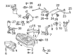
 2005 Toyota Prius Fuel Tank
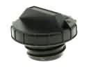 2005 Toyota Prius Gas Cap
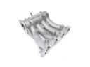 2005 Toyota Prius Intake Manifold
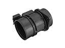 2005 Toyota Prius Mass Air Flow Sensor
 2005 Toyota Prius Cruise Control Switch
 2005 Toyota Prius Fuel Filler Neck
 2005 Toyota Prius Fuel Injector O-Ring
 2005 Toyota Prius Fuel Line Clamps
 2005 Toyota Prius Fuel Pump Gasket
 2005 Toyota Prius Fuel Pump Seal
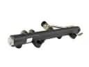 2005 Toyota Prius Fuel Rail
 2005 Toyota Prius Fuel Tank Strap