My Garage
Cart

OEM 2005 Toyota 4Runner ABS Control Module

Anti Lock Brake Control Module
  • Select Vehicle by Model
  • Select Vehicle by VIN
Select Vehicle by Model
Make
Model
Year
or
Select Vehicle by VIN
For the most accurate results, select vehicle by your VIN (Vehicle Identification Number).

1 ABS Control Module found

  • 2005 Toyota 4Runner ABS Control Module - 89540-35320
    2005 Toyota 4Runner ABS Control Module Diagram - 89540-35320
    View related parts

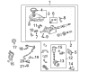
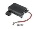
    2005 Toyota 4Runner Control Module

    Part Number: 89540-35320
    $1902.44 MSRP: $2394.81
    You Save: $492.37 (21%)
    Ships in 1-3 Business Days
    ADD TO CART
    Product Specifications
    • Other Name: Computer Assembly, Skid; ABS Control Module; Computer Assembly, Skid Control
    • Part Name Code: 89540
    • Item Weight: 1.60 Pounds
    • Item Dimensions: 8.2 x 6.2 x 3.6 inches
    • Condition: New
    • Fitment Type: Direct Replacement
    • SKU: 89540-35320
    • Warranty: This genuine part is guaranteed by Toyota's factory warranty.
    More Info
    Fits the following 2005 Toyota 4Runner Submodels:
    • Limited, Sport, SR5 | 6 Cyl 4.0 L GAS, 8 Cyl 4.7 L GAS

2005 Toyota 4Runner ABS Control Module

Looking for affordable OEM 2005 Toyota 4Runner ABS Control Module? Explore our comprehensive catalogue of genuine 2005 Toyota 4Runner ABS Control Module. All our parts are covered by the manufacturer's warranty. Plus, our straightforward return policy and speedy delivery service ensure an unparalleled shopping experience. We look forward to your visit!

2005 Toyota 4Runner Parts Questions & Experts Answers

  • Q: How to overhaul the ABS Control Module for Antilock Brakes on 2005 Toyota 4Runner?
    A: The Hydraulic Control Assembly for Antilock Brakes needs to receive lithium soap base glycol grease treatment on specified parts before examining if the brake actuator tube No.1 sustains high-pressure deformation. Turn off the ignition switch and perform brake pedal depression more than 20 times before beginning the work. First drain all brake fluid when you encounter painted surfaces then detach the front door scuff plate LH and front floor footrest followed by cowl side trim board LH and instrument panel finish plate and instrument panel finish panel sub-assembly lower and steering column hole cover by using the clips for removal. Begin by unharnessing the 3 connectors attached to the brake master cylinder followed by using SST 09023-00101 to detach the 4 brake lines. The push rod pin requires removing its clip before proceeding. Extract the brake master cylinder by removing its 4 nuts before eliminating the brake booster gasket. Brake actuators with 5 mm hexagon wrenches can be used to detach bracket no:1 before removing wire connections to the warning switch. The first step for repairing the brake master cylinder reservoir sub-assembly involves hitting the pin with a pin punch and hammer while unscrewing and pulling it out before removing the master cylinder reservoir filler cap and the three reservoir grommets. Workers should use needle nose pliers to unhook clips before they remove the brake actuator hose then employ SST to use on brake actuator tube No.1. The brake booster with accumulator pump assembly requires removal of two plugs and disconnecting master cylinder solenoid wire harnesses before extracting the assembly together with its two brake booster pump collars and bushes. The technician should detach brake booster pump bracket No.2 using a 5 mm hexagon wrench before removing brake actuator bracket No.3. Place the brake booster with accumulator pump assembly into a vise while securing it so you can remove the brake booster accumulator assembly with its O-ring to prevent any foreign entries into the pump. The brake booster pump assembly motor functionality can be checked through battery lead connection during inspection. Cut the brake booster accumulator assembly using safety glasses between the points designated as A and B to dispose of it properly. Releasing the 6 bolts and gasket for master cylinder solenoid enables you to detach it from the brake system. Next loosen the lock nuts to move the push rod clevis and rod operating adapter. To access both the master cylinder boot and the brake master cylinder kit use the piston push method after removing the C-ring and successfully withdraw the piston directly. You should apply lithium soap base glycol grease to the piston before installing the new brake master cylinder kit together with its snap ring. Subscribe the master cylinder boot along with push rod clevis by applying 26 Nm of torque to the lock nuts. Fit the master cylinder solenoid together with a new gasket and torque it at 32 Nm and then install the brake booster accumulator assembly with a new O-ring at 57 Nm. The mechanic should torque brake actuator bracket No.3 and brake booster pump bracket No.2 to 7.8 Nm. Secure all brake booster with accumulator pump assembly components in place before tightening the brake actuator tube No.1 to 14 Nm using SST 09023-00101 at SST. After attaching the brake actuator hose and reservoir grommets one should install the brake master cylinder reservoir sub-assembly by screwing it at 1.7 Nm tension followed by filling the reservoir. The installation includes braking actuator bracket No.1 and brake booster gasket along with brake master cylinder at 14 Nm while verifying proper connection and adequate torque of all brake lines. After reversing the component removal sequence you must install the push rod pin, steering column hole cover followed by all earlier components before bleeding the brake booster, brake line and master cylinder solenoid as you check brake pedal height and free play, reserve distance, fluid level, leakage and master cylinder operating condition.

Related 2005 Toyota 4Runner Parts