×
ToyotaParts- Hello
- Login or Register
- Quick Links
- Live Chat
- Track Order
- Parts Availability
- RMA
- Help Center
- Contact Us
- Shop for
- Toyota Parts
- Scion Parts
My Garage
My Account
Cart
OEM 2004 Toyota Land Cruiser ABS Control Module
Anti Lock Brake Control Module- Select Vehicle by Model
- Select Vehicle by VIN
Select Vehicle by Model
orMake
Model
Year
Select Vehicle by VIN
For the most accurate results, select vehicle by your VIN (Vehicle Identification Number).
1 ABS Control Module found

2004 Toyota Land Cruiser Control Module
Part Number: 89540-60430$2300.24 MSRP: $2895.55You Save: $595.31 (21%)Ships in 1-3 Business DaysProduct Specifications- Other Name: Computer Assembly, Skid; ABS Control Module; Computer Assembly, Skid Control
- Replaces: 89540-60390
- Part Name Code: 89540
- Item Weight: 1.60 Pounds
- Item Dimensions: 8.2 x 6.6 x 3.8 inches
- Condition: New
- Fitment Type: Direct Replacement
- SKU: 89540-60430
- Warranty: This genuine part is guaranteed by Toyota's factory warranty.
2004 Toyota Land Cruiser ABS Control Module
Looking for affordable OEM 2004 Toyota Land Cruiser ABS Control Module? Explore our comprehensive catalogue of genuine 2004 Toyota Land Cruiser ABS Control Module. All our parts are covered by the manufacturer's warranty. Plus, our straightforward return policy and speedy delivery service ensure an unparalleled shopping experience. We look forward to your visit!
2004 Toyota Land Cruiser ABS Control Module Parts Q&A
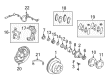
- Q: How to disassemble the ABS control module for antilock brakes on 2004 Toyota Land Cruiser?A: The hydraulic control assembly for antilock brakes disassembly process begins by mounting the hydraulic brake booster into a vise as per requirements of Special Service Tools: 09630-00014 (09631-00142), 09950-60010 (09951-00180, 09951-00190). Start by disconnecting the fluid level warning switch connector and removing its bolt while taking out the clamp. The next step involves removing the reservoir cap and succeeding reservoir removal by cautiously untightening the set screws to a torque of 1.7 Nm (17.5 kgf-cm, 15.2 inch lbs.). After that, the 3 grommets can be taken out. Start by loosening the lock nut before unfastening the clevis and lock nut sequence which requires a torque force of 25 Nm (260 kgf-cm, 19 ft. lbs.). This action allows you to remove the cylinder boot from service. The brake actuator tube No. 1 should be removed using Special Service Tool: 09023-00100 while rotating it to 15 Nm (155 kgf-cm, 11 ft. lbs.). The booster pump and assembly requires removal of the actuator hose followed by disconnection of the 4 screws and wire harness and subsequent removal of the 2 accumulator bracket bolts and 2 booster pump motor assembly bolts and bolt from No.1 pump bracket and the 2 bolts from No. 2 pump bracket with their corresponding washers, cushions, collars and sleeve. Professional technicians should uninstall the master cylinder pressure sensor using a torque wrench of 81 Nm (830 kgf-cm, 60 ft. lbs.) and the proper replacement part should be part No: 89637-30050. To remove the piston workers should push it in with a screwdriver followed by driving a pin to push out the snap ring before extracting the piston directly to protect the cylinder bore. The technician should remove the accumulator from the booster pump using a torque of 54 Nm (550 kgf-cm, 36 ft. lbs.) with Special Service Tool: 09318-12010 before removing the silencer tube together with its spring and O-ring. Check the hydraulic brake booster pump motor operation through connection of battery leads to the pump motor terminals. Placing the accumulator in a vise while using a cloth as protection cut its body with a saw on the stretch section only to release gas once the cut exceeds the dead length. Reassembly occurs in reverse order of disassembly with a requirement to modify the accumulator bracket settings where A + B must be 4.1 mm (0.161 inch) or less yet C needs to be between 0.3 - 3.8 mm (0.012 - 0.150 inch), indicating that more than 0.3 mm (0.012 inch) clearance must exist between A and B.
Related 2004 Toyota Land Cruiser Parts
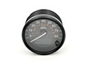 2004 Toyota Land Cruiser Speedometer
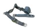 2004 Toyota Land Cruiser Seat Belt
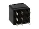 2004 Toyota Land Cruiser ABS Relay
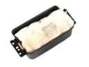 2004 Toyota Land Cruiser Air Bag
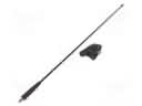 2004 Toyota Land Cruiser Antenna
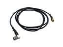 2004 Toyota Land Cruiser Antenna Cable
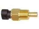 2004 Toyota Land Cruiser Coolant Temperature Sensor
 2004 Toyota Land Cruiser Dimmer Switch
 2004 Toyota Land Cruiser Knock Sensor
 2004 Toyota Land Cruiser Mirror Switch
 2004 Toyota Land Cruiser Power Window Switch
 2004 Toyota Land Cruiser Relay