×
ToyotaParts- Hello
- Login or Register
- Quick Links
- Live Chat
- Track Order
- Parts Availability
- RMA
- Help Center
- Contact Us
- Shop for
- Toyota Parts
- Scion Parts
My Garage
My Account
Cart
OEM 2004 Toyota Corolla Shock Absorber
Suspension Shock Absorber- Select Vehicle by Model
- Select Vehicle by VIN
Select Vehicle by Model
orMake
Model
Year
Select Vehicle by VIN
For the most accurate results, select vehicle by your VIN (Vehicle Identification Number).
3 Shock Absorbers found


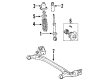
2004 Toyota Corolla Shock Absorber
Part Number: 48530-09F90$114.22 MSRP: $160.33You Save: $46.11 (29%)Ships in 1-3 Business DaysProduct Specifications- Other Name: Absorber Assembly Set, S; Rear Shock Absorber; Suspension Strut Kit; Complete Strut; Absorber Assembly, Shock, Rear Passenger Side; Absorber Assembly, Shock, Rear Driver Side; Shock
- Manufacturer Note: MARK 48530-02341
- Replaces: 48530-09750
- Item Weight: 6.10 Pounds
- Item Dimensions: 26.1 x 6.8 x 5.7 inches
- Condition: New
- Fitment Type: Direct Replacement
- SKU: 48530-09F90
- Warranty: This genuine part is guaranteed by Toyota's factory warranty.

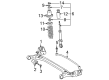
2004 Toyota Corolla Shock Absorber
Part Number: 48530-A9560$113.16 MSRP: $158.84You Save: $45.68 (29%)Ships in 1-3 Business DaysProduct Specifications- Other Name: Absorber Assembly Set, S; Rear Shock Absorber; Suspension Strut Kit; Complete Strut; Strut; Absorber Assembly, Shock, Rear Passenger Side; Absorber Assembly, Shock, Rear Driver Side; Shock
- Manufacturer Note: MARK 48530-AB031
- Replaces: 48530-A9160, 48530-A9440, 48530-80281, 48530-A9270
- Item Weight: 5.30 Pounds
- Item Dimensions: 26.6 x 6.6 x 5.9 inches
- Condition: New
- Fitment Type: Direct Replacement
- SKU: 48530-A9560
- Warranty: This genuine part is guaranteed by Toyota's factory warranty.

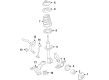
2004 Toyota Corolla Strut Mount, Front Driver Side
Part Number: 48520-A9180$124.54 MSRP: $176.30You Save: $51.76 (30%)Product Specifications- Other Name: Absorber Assembly, Shock; Suspension Strut, Front Left; Strut Assembly Kit; Complete Strut Kit; Shock Absorber; Strut; Absorber Assembly, Shock, Front Driver Side
- Manufacturer Note: MARK 48520-AB031
- Position: Front Driver Side
- Replaces: 48520-A9150
- Part Name Code: 48520
- Item Weight: 11.40 Pounds
- Item Dimensions: 26.9 x 8.2 x 7.6 inches
- Condition: New
- Fitment Type: Direct Replacement
- SKU: 48520-A9180
- Warranty: This genuine part is guaranteed by Toyota's factory warranty.
2004 Toyota Corolla Shock Absorber
Looking for affordable OEM 2004 Toyota Corolla Shock Absorber? Explore our comprehensive catalogue of genuine 2004 Toyota Corolla Shock Absorber. All our parts are covered by the manufacturer's warranty. Plus, our straightforward return policy and speedy delivery service ensure an unparalleled shopping experience. We look forward to your visit!
2004 Toyota Corolla Shock Absorber Parts Q&A
- Q: How to overhaul the front shock absorber with coil spring on 2004 Toyota Corolla?A: Start the front shock absorber coil spring overhaul by removing the front wheel before disconnecting the front stabilizer link assembly LH which requires nut removal but only proceed if the ball joint stays fixed with the nut by using a hexagon (6 mm) wrench to immobilize the stud. You need to disconnect the front flexible hose by removing its bolt and removing both the front flexible hose No. 1 and speed sensor front LH when your vehicle has ABS installed yet only remove the front flexible hose if ABS is not present. Remove the front shock absorber with coil spring from the vehicle by detaching its lower two bolts and nuts followed by three upper nuts at the shock absorber assembly front LH then pull out the assembly. Fix the front shock absorber with coil spring by installing two nuts and a bolt to the bracket at the lower side but place it into a vise for safety. Users need to remove the front suspension support dust cover LH before compressing the front coil spring LH with Special Service Tool: 09727-30021 instead of using an impact wrench to protect the tool from harm. The front coil spring seat upper LH can be retrieved with Special Service Tool: 09729-22031 while supporting the nut at its front end before extracting the front suspension support sub-assembly LH and its respective components including front suspension support LH dust seal followed by front coil spring seat upper LH and front coil spring insulator upper LH preceding the removal of front coil spring LH and front spring bumper LH and finally the front coil spring insulator lower LH. Through shock absorber assembly front LH resistance and sound checks during rod compression and extension you can detect abnormalities; install new parts if any defects are present. The procedure to install the shock absorber assembly front LH begins with positioning the front coil spring insulator lower LH onto the shock absorber assembly then attaching the front spring bumper LH to the shock absorber piston rod while using Special Service Tool: 09727-30021 to compress the front coil spring LH. The installation begins with fitting the lower end of front coil spring LH into the spring lower seat gap followed by inserting the front coil spring insulator upper LH and front coil spring seat upper LH which must have the mark oriented towards the outside of the vehicle. When installing the new nut to hold front coil spring seat upper LH the Special Service Tool: 09729-22031 helps secure the front suspension support LH while tightening the nut to 47 Nm (479 kgf-cm, 35 ft. lbs.). Pass the tool then place the LH side front suspension support dust cover while you fill the sub-assembly with MP grease No.2 staying away from the upper support rubber surface. First install the shock absorber with upper-side bolts, nuts and upper-side torques to 39 Nm (398 kgf-cm, 29 ft. lbs.) and then install lower-side bolts, nuts followed by a torque of 153 Nm (1,560 kgf-cm, 113 ft. lbs.) while carefully stopping bolt rotation during lower-side nut torquing. Workers should reinstall the front flexible hose with the speed sensor front LH bolt when your ABS system is installed but only the front flexible hose when no ABS is used. Torque the hose to 29 Nm (296 kgf-cm, 21 ft. lbs.). The front stabilizer link assembly requires installation of the nut onto its LH side followed by torqueing to 74 Nm (755 kgf-cm, 55 ft. lbs.). Use a hexagon wrench (6 mm) to grip the stud if the ball joint turns with the nut. To finish the job replace the front wheel and torque it at 103 Nm (1,050 kgf-cm, 76 ft. lbs.) before checking and adjusting the front wheel alignment. The front LH shock absorber disposal requires total piston rod extension followed by cylinder drilling to release internal gas while adopting safety measures against flying drill pieces; the released substance remains odorless, harmless and colorless.
Related 2004 Toyota Corolla Parts
 2004 Toyota Corolla Ball Joint
 2004 Toyota Corolla Control Arm Bushing
 2004 Toyota Corolla Steering Knuckle
 2004 Toyota Corolla Alignment Bolt
 2004 Toyota Corolla Axle Shaft
 2004 Toyota Corolla Bump Stop
 2004 Toyota Corolla Control Arm Bolt
 2004 Toyota Corolla Front Cross-Member
 2004 Toyota Corolla Shock And Strut Mount
 2004 Toyota Corolla Shock and Strut Boot
 2004 Toyota Corolla Strut Housing
 2004 Toyota Corolla Sway Bar Bushing