×
ToyotaParts- Hello
- Login or Register
- Quick Links
- Live Chat
- Track Order
- Parts Availability
- RMA
- Help Center
- Contact Us
- Shop for
- Toyota Parts
- Scion Parts
My Garage
My Account
Cart
OEM 2003 Toyota Prius Brake Caliper
Caliper- Select Vehicle by Model
- Select Vehicle by VIN
Select Vehicle by Model
orMake
Model
Year
Select Vehicle by VIN
For the most accurate results, select vehicle by your VIN (Vehicle Identification Number).
2 Brake Calipers found

2003 Toyota Prius Caliper, Passenger Side
Part Number: 47730-12490$231.24 MSRP: $330.16You Save: $98.92 (30%)Ships in 1-3 Business DaysProduct Specifications- Other Name: Cylinder Assembly, Disc; Disc Brake Caliper, Front Right; Cylinder Assembly, Front Disc Brake, Passenger Side; Brake Caliper
- Position: Passenger Side
- Part Name Code: 47730
- Item Weight: 11.80 Pounds
- Item Dimensions: 10.3 x 7.8 x 5.4 inches
- Condition: New
- Fitment Type: Direct Replacement
- SKU: 47730-12490
- Warranty: This genuine part is guaranteed by Toyota's factory warranty.
2003 Toyota Prius Caliper, Driver Side
Part Number: 47750-12490$226.62 MSRP: $323.55You Save: $96.93 (30%)Ships in 1-3 Business DaysProduct Specifications- Other Name: Cylinder Assembly, Disc; Disc Brake Caliper, Front Left; Cylinder Assembly, Disc Brake, Driver Side; Brake Caliper
- Position: Driver Side
- Part Name Code: 47750
- Item Weight: 12.20 Pounds
- Item Dimensions: 10.3 x 7.8 x 5.4 inches
- Condition: New
- Fitment Type: Direct Replacement
- SKU: 47750-12490
- Warranty: This genuine part is guaranteed by Toyota's factory warranty.
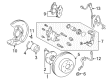
2003 Toyota Prius Brake Caliper
Looking for affordable OEM 2003 Toyota Prius Brake Caliper? Explore our comprehensive catalogue of genuine 2003 Toyota Prius Brake Caliper. All our parts are covered by the manufacturer's warranty. Plus, our straightforward return policy and speedy delivery service ensure an unparalleled shopping experience. We look forward to your visit!
2003 Toyota Prius Brake Caliper Parts Q&A
- Q: How to service and repair the brake caliper on 2003 Toyota Prius?A: The brake caliper servicing process starts with unscrewing both the set ring and cylinder boot through the use of a screwdriver. After positioning a cloth between the caliper and piston you can extract the piston with compressed air while avoiding placing fingers before the piston's location. User a screwdriver to remove the piston seal before taking out the sequence of sliding pins from the torque plate together with the removal of the 2 dust boots. The standard pad lining thickness should be 11.0 mm (0.433 inch) and the minimum should be 1.0 mm (0.039 inch) for a proper inspection. Therefore, replace the pad if the thickness measurement reveals equality or decrease or if it exhibits serious uneven wear. A micrometer should measure disc thickness because the standard stands at 22.0 mm (0.866 inch) but the minimum is set at 20.0 mm (0.787 inch); disc replacement must occur with any thickness reaching the minimum limit or when scoring or uneven wear becomes unbearable. A dial indicator enables the measurement of disc runout at 10 mm (0.39 inch) from the outer edge and the maximum allowable runout measurement stands at 0.05 mm (0.0020 inch). When this value is surpassed, verify bearing axial play and axle hub runout before disc assessment for adjustment or grinding. Proceed with disc adjustment by removing the 2 bolts with torque plate from the knuckle before you can take out the hub nuts and disc. Install the disc at a 1/4 turned position relative to its initial hub placement while tightening the hub nuts to 103 Nm (1,050 kgf-cm, 76 ft. lbs.). Measure disc runout after finishing disc installation at the ideal position and record runout results and disc placement. Repeat this procedure until you find the most optimal disc sitting. The preferred disc position for installation will be the one that shows a minimum runout less than 0.05 mm (0.0020 inch); otherwise replace the disc and perform the runout check again. Complete the installation by putting on the torque plate then tighten the mounting bolts to 107 Nm (1,090 kgf-cm, 79 ft. lbs.). Reassembly requires the use of lithium soap base glycol grease which should be applied to noted components as the process goes backward from disassembly.
Related 2003 Toyota Prius Parts
 2003 Toyota Prius Speed Sensor
 2003 Toyota Prius Wheel Hub
 2003 Toyota Prius ABS Pump And Motor Assembly
 2003 Toyota Prius Backing Plate
 2003 Toyota Prius Brake Caliper Piston
 2003 Toyota Prius Brake Disc
 2003 Toyota Prius Brake Drum
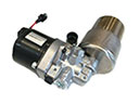 2003 Toyota Prius Brake Fluid Pump
 2003 Toyota Prius Parking Brake Shoe
 2003 Toyota Prius Spindle Nut
 2003 Toyota Prius Wheel Cylinder
 2003 Toyota Prius Wheel Stud